Automatic gain control method and device for power carrier communication system

A technology of automatic gain control and power carrier communication, which is applied in the direction of distribution line transmission system, etc., can solve the problems of carrier signal reflection, standing wave, power consumption and large scale, carrier signal attenuation difference, etc., to achieve strong immunity and prevent The effect of misadjustment

Active Publication Date: 2017-03-29
BEIJING XIAOCHENG TECH CO LTD
View PDF5 Cites 14 Cited by
  • Summary
  • Abstract
  • Description
  • Claims
  • Application Information

AI Technical Summary

Problems solved by technology

[0003] The distance of different communication unit modules on the power line is quite different, which brings about a huge difference in the attenuation of the carrier signal; due to the impedance mismatch, the carrier signal will have complex phenomena such as reflection and standing waves, which makes the attenuation characteristics of the power line more complicated;
[0004] On the other hand, there are various noises such as colored background noise, narrow-band interference noise, periodic impulse noise and random impulse noise on the power line, and the instantaneous power of the noise is often much higher than that of the carrier signal. In this case, the gain will be adjusted according to the change of the noise power, so that the amplitude of the carrier signal that has been annihilated by the noise will jump, and the signal-to-noise ratio of the receiving demodulation will further deteriorate.
[0005] In addition, in order to ensure the stability of gain control, the traditional automatic gain control technology generally performs feedback control through power, energy or effective value, which requires multiplication operations. When the ADC sampling frequency is high, the power consumption and scale are relatively large.

Method used


Image

  • Automatic gain control method and device for power carrier communication system
  • Automatic gain control method and device for power carrier communication system
  • Automatic gain control method and device for power carrier communication system

Examples


Embodiment Construction

[0038] In order to make the advantages and technical solutions of the present invention easier to understand, the technical solutions in the embodiments of the present invention will be further described in detail below in conjunction with the drawings in the embodiments.

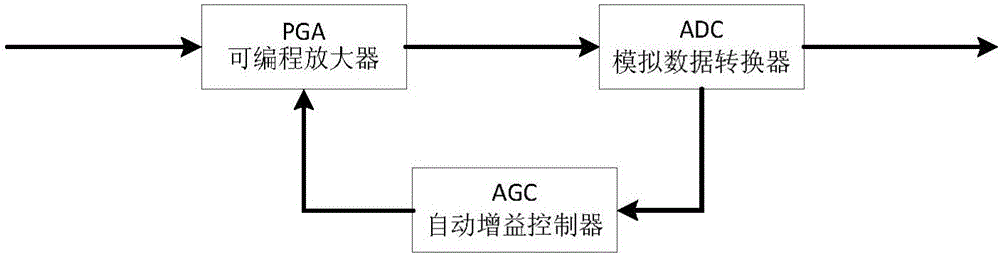
[0039] Such as figure 1 As shown, the power line communication receiving unit module adjusts the amplification factor of the programmable gain amplifier (programmable gain amplifier, PGA) through automatic gain control (Automatic GainControl, AGC), and properly amplifies or reduces the received carrier signal to ensure that the ADC sampling signal Accuracy is sufficient without amplitude saturation for long periods of time.

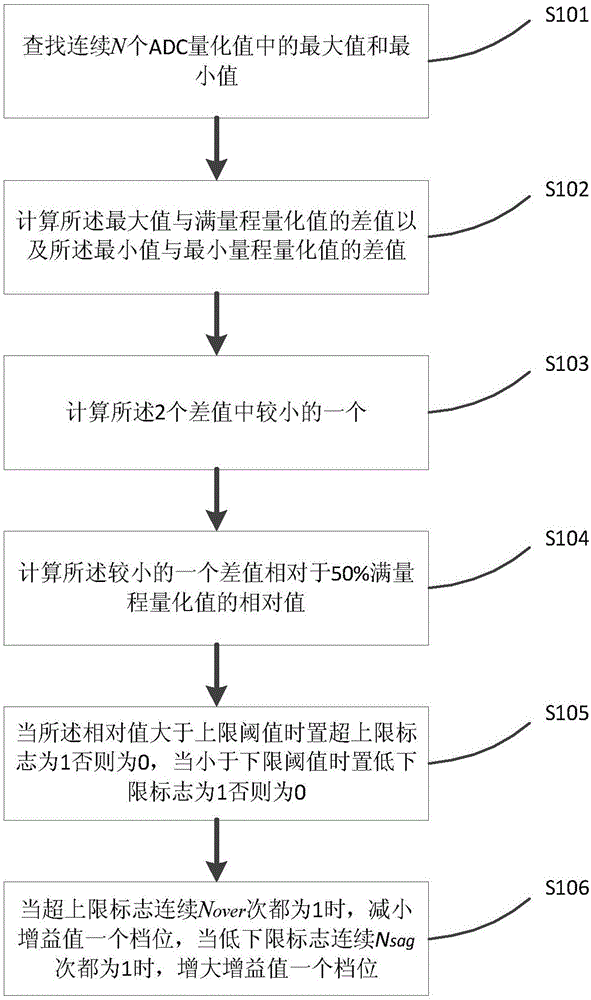
[0040] Such as figure 2 As shown, a method for automatic gain control of a power carrier communication system includes the following steps:

[0041] Step S201: Find the maximum value Q among N consecutive ADC quantization values max,n and minimum Q min,n , expressed as follows:

...


PUM


Abstract

The invention discloses an automatic gain control method and device for a power carrier communication system. The method comprises the following steps of: finding a maximum value and a minimum value in continuous N ADC quantized values; calculating a difference value between the maximum value and a full-range quantized value and a difference value between the minimum value and a minimum-range quantized value; calculating the relative small value in two difference values; calculating a relative value of the relative small difference value corresponding to the 50% full-range quantized value; when the relative value is greater than an upper limit threshold value, setting an ultra-upper-limit mark to 1, otherwise, setting the ultra-upper-limit mark to 0, when the relative value is less than a lower limit threshold value, setting a low-lower-limit mark to 1, and otherwise, setting the low-lower-limit mark to 0; and, when the ultra-upper-limit mark is 1 for successive N<over> times, reducing one level of a gain value, and, when the low-lower-limit mark is 1 for successive N<sag> times, increasing one level of the gain value. The automatic gain control method and device disclosed by the invention have high immunocompetence to pulse noise in a low signal-to-noise ratio; and simultaneously, the automatic gain control method and device are low in complexity, and easy to realize.

Description

technical field [0001] The invention relates to the technical field of power line carrier communication, in particular to an automatic gain control method and device for a power carrier communication system. Background technique [0002] Power Line Communication (PLC), referred to as PLC, is a unique communication method of the power system. It refers to a data transmission technology that uses the existing power line as a communication medium. The carrier signal is transmitted along the power line, and the receiving end restores the original information data by demodulating the carrier signal. [0003] The distance of different communication unit modules on the power line is quite different, which brings about a huge difference in the attenuation of the carrier signal; due to the impedance mismatch, the carrier signal will have complex phenomena such as reflection and standing waves, which makes the attenuation characteristics of the power line more complicated; [0004] O...

Claims


Application Information

Patent Timeline
Patent Type & Authority Applications(China)
IPC IPC(8): H04B3/58
CPCH04B3/58
Inventor 水永辉
Owner BEIJING XIAOCHENG TECH CO LTD
Why Eureka
Try Eureka