Vibrating-press-type pile construction method and vibrating hammer equipment therefor

A construction method and technology of vibrating hammer, applied in sheet pile wall, foundation structure engineering, construction, etc., can solve the problems of installation accident, difficult mechanical equipment, not meeting installation conditions, etc., to ensure quality, increase compression resistance and The effect of pullout resistance

Inactive Publication Date: 2017-04-05
刘献刚
View PDF7 Cites 1 Cited by
  • Summary
  • Abstract
  • Description
  • Claims
  • Application Information

AI Technical Summary

Problems solved by technology

However, the vibrating pipe sinking method used in the prior art is used to make cast-in-situ piles. Vibratory hammer equipment is used to connect the hammer body with the inner or outer pipe used to form the pile hole, and the inner and outer pipes are sunk by vibration. to form pile holes; for environments with relatively dense soil, in order to ensure the construction progress, the working power of the vibratory hammer is usually increased to form pile holes; Dense, after the concrete is poured, the speed of

Method used


Image

  • Vibrating-press-type pile construction method and vibrating hammer equipment therefor
  • Vibrating-press-type pile construction method and vibrating hammer equipment therefor

Examples


Embodiment 1

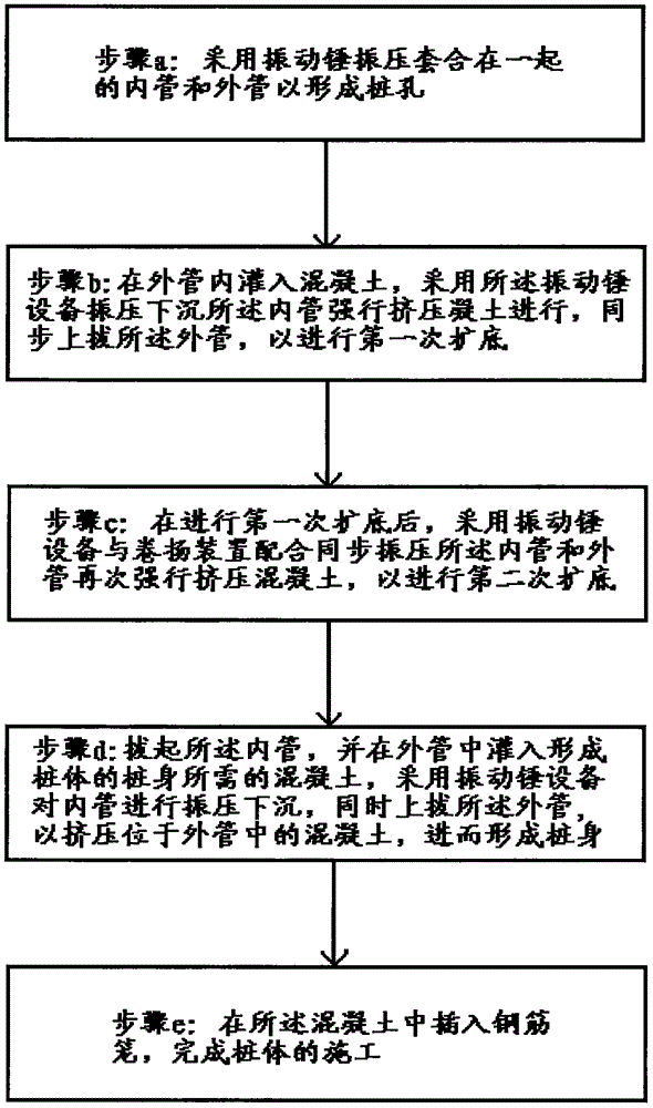
[0029] Such as figure 1 As shown, a vibratory pressure pile construction method of the present embodiment includes the following steps: a. Using a vibratory hammer device, using the self-weight of the hammer body of the vibratory hammer device to vibrate the inner tube and the outer tube that are nested together tube, realize sinking at the pile position to form the pile hole; b, pull up the inner tube, pour the concrete required to form the pile body into the outer tube, and use the vibratory hammer The equipment vibrates and sinks the inner pipe to forcibly squeeze the concrete in the outer pipe, and pulls the outer pipe synchronously to perform the first bottom expansion to form a preliminary pile bottom expansion head; c. After the first bottom expansion, the vibratory hammer equipment and the hoisting device are used to synchronously vibrate the inner pipe and the outer pipe to forcibly squeeze the concrete again, so as to perform the second bottom expansion to form a dia...

Embodiment 2

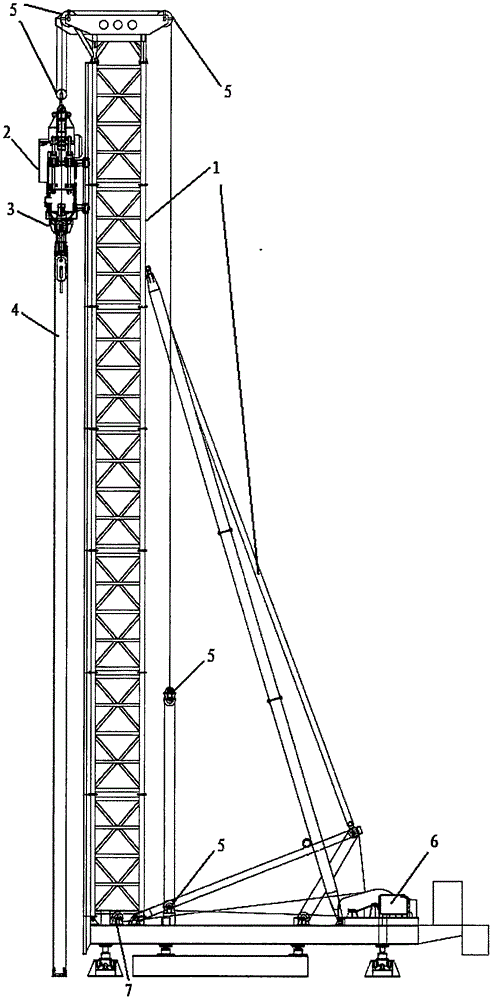
[0039] Such as figure 2 As shown, a vibratory hammer device for the above-mentioned vibratory pressure type pile construction method includes: a bracket 1, a first pulley assembly 5 installed on the bracket 1; a vibratory hammer 2, a first end and the first pulley assembly 5, the second end has a fixing structure 3 for fixing the sleeve 4, wherein the sleeve 4 includes an inner tube and an outer tube, and the inner tube and the outer tube are nested together in the embodiment; It also includes: a second pulley assembly 7 installed on the bracket 1; a hoisting device 6 installed on the bracket, the hoisting device is connected with the vibratory hammer through the second pulley assembly, and is suitable for for applying a vertical downward force to the vibratory hammer.

[0040] In the vibratory hammer device of this embodiment, the fixing structure is preferably a hydraulic clamp.

[0041] In the vibratory hammer device of this embodiment, the vibratory hammer is preferably...


PUM


Abstract

The invention discloses a vibrating-press-type sinking construction method. The vibrating-press-type sinking construction method is characterized in that according to the compactness of soil, vibrating hammer equipment is adopted, and by use of the self-weights of a hammer body of the vibrating hammer equipment and a balancing weight detachably mounted on the hammer body and corresponding to the compactness of the soil, at least one of an inner pipe and an outer pipe which are nested together is subjected to vibrating-press operation to the designed standard height so as to realize pipe sinking. According to the design, the self-weight of the corresponding balancing weight is increased or adjusted on the basis of the conventional vibrating hammer equipment according to different soil compactness to achieve the purpose that one set of the vibrating hammer equipment adapts to construction in different soil characteristics to meet the design requirements, so that not only is the construction efficiency guaranteed, but also the construction cost is lowered. The invention also discloses a vibrating-press-type pile construction method adopting the vibrating-press-type sinking construction method and the vibrating hammer equipment for the vibrating-press-type pile construction method.

Description

technical field [0001] The invention relates to a pile body construction method and equipment for a building foundation, in particular to a vibratory pressure type pile body construction method and vibratory hammer equipment used in the construction method. Background technique [0002] At present, there are a variety of construction methods for building piles in the prior art, and these construction methods also have their own advantages and disadvantages. For example, when making cast-in-place piles with immersed tubes, two methods of hammering sinking tubes and vibrating tube sinking can be used. The former It is mostly used for general cohesive soil, silty soil, sandy soil and artificial filled soil foundation. In addition to the above scope, the latter can also be used for slightly dense and medium dense gravel soil foundation. The way of hammering the immersed tube will produce a lot of noise, especially in the construction in the city, the noise generated will have a ...

Claims


Application Information

Patent Timeline
IPC IPC(8): E02D5/38E02D5/44E02D7/18
CPCE02D5/38E02D5/385E02D5/44E02D7/18E02D2300/002
Inventor 刘献刚屈峰刘国贤薛小波
Owner 刘献刚
Why Eureka
Try Eureka