Turbofan engine and fan blade thereof

A turbofan and fan blade technology, which is applied in the direction of machines/engines, liquid fuel engines, mechanical equipment, etc., can solve the problems of desoldering of welding seams, increasing the quality of blades, and damage of blades, so as to improve impact resistance and increase damping effect, the effect of increasing path length

Active Publication Date: 2017-04-05
AECC COMML AIRCRAFT ENGINE CO LTD
View PDF9 Cites 10 Cited by
  • Summary
  • Abstract
  • Description
  • Claims
  • Application Information

AI Technical Summary

Problems solved by technology

When the hollow blade structure produced by superplastic molding / diffusion welding process is used, the impact of foreign objects, especially small hard objects, will easily cause desoldering of the weld position, which will cause damage or even failure of the blade
If the wall plate or core plate of the fan blade is thickened, the mass of the blade will be increased

Method used


Image

  • Turbofan engine and fan blade thereof
  • Turbofan engine and fan blade thereof
  • Turbofan engine and fan blade thereof

Examples


Embodiment Construction

[0026] The embodiment of the present invention describes a fan blade of a turbofan engine, the ability of the blade to resist the impact of foreign objects is improved, and the quality does not need to be increased, the shape of the blade does not need to be changed, and the processing technology is easy to realize.

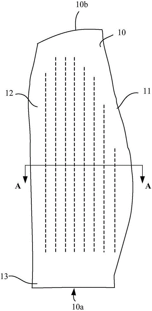
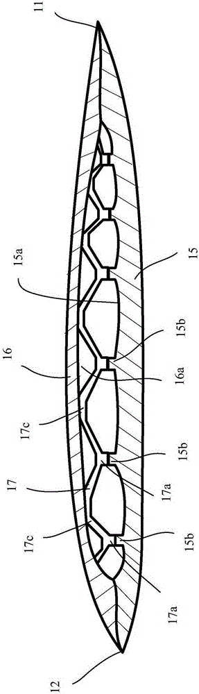
[0027] figure 1 An outline view of a fan blade of a turbofan engine according to an embodiment of the present invention is shown. figure 2 A-A sectional view showing a fan blade of a turbofan engine according to an embodiment of the present invention. refer to figure 1 and figure 2 As shown, the blade 10 can be divided into a leading edge 11 , a trailing edge 12 and a tenon 13 . The entire blade 10 is a hollow structure, including a pressure side wall plate 15 , a suction side wall plate 16 , and a core plate structure 17 . The pressure side wall plate 15 and the suction side wall plate 16 are combined to form a cavity 18 , and the core plate structure 17 i...


PUM


Abstract

The invention relates to a turbofan engine and a fan blade thereof. The fan blade comprises a pressure-side wall plate, a suction-side wall plate and a core plate structure between the pressure-side wall plate and the suction-side wall plate, wherein the core plate structure is provided with a plurality of first joint parts; a plurality of lug bosses are arranged on the inner side surface of the pressure-side wall plate respectively and correspond to the first joint parts in position; the first joint parts are jointed with the lug bosses; and the thickness ratio of each lug boss to the core plate structure ranges from 0.5:1 to 1:1.

Description

technical field [0001] The present invention relates to turbofan engines, and more particularly to fan blades for turbofan engines. Background technique [0002] Most modern high-speed aircraft use jet engines. The principle is to inhale air, mix it with fuel, ignite it, and expel the expanded air backwards. The reaction force pushes the aircraft forward. Turbofan engine (turbofan engine), as a kind of jet engine, is the engine of choice for subsonic aircraft, especially civil aircraft. Part of the air inhaled by the turbofan engine is blown from the outer duct, and part of it is sent to the core engine of the inner duct. The fan at the front end of the engine achieves the purpose of improving the propulsion efficiency of the jet engine by reducing the exhaust velocity. [0003] Since the fan blades of the turbofan engine are located at the front end of the engine, they are vulnerable to impacts from flying birds, ice, hail and other foreign objects. When the hollow blade...

Claims


Application Information

Patent Timeline
Patent Type & Authority Applications(China)
IPC IPC(8): F04D29/38
Inventor 曹源
Owner AECC COMML AIRCRAFT ENGINE CO LTD
Why Eureka
Try Eureka