Partial discharge direction finding method based on ultrahigh-frequency phased array principle in substation

A partial discharge and ultra-high frequency technology, which is applied in the field of partial discharge direction finding based on the principle of ultra-high frequency phased array, and can solve the problem of low resolution threshold and estimation deviation of direction finding accuracy, unfavorable inspection, and heavy maintenance workload. problem, to improve the anti-interference ability and direction finding accuracy, great practical value, and improve the effect of direction finding accuracy

Active Publication Date: 2017-04-05
XI AN JIAOTONG UNIV +2
View PDF7 Cites 16 Cited by
  • Summary
  • Abstract
  • Description
  • Claims
  • Application Information

AI Technical Summary

Problems solved by technology

At present, the partial discharge detection based on ultra-high frequency technology carried out at home and abroad usually installs the sensor on specific single equipment such as gas-insulated combined electrical equipment and transformers. The partial discharge detection and direction finding of substation equipment are mainly for specific equipment, and all power equipment in the substation may have partial discharge. If a partial discharge monitoring system is installed on secondary equipment such as bushings and circuit breakers, the cost is extremely high and the maintenance workload is also heavy. Therefore, relevant scholars at home and abroad A partial discharge detection and location system in open substati...

Method used


Image

  • Partial discharge direction finding method based on ultrahigh-frequency phased array principle in substation
  • Partial discharge direction finding method based on ultrahigh-frequency phased array principle in substation
  • Partial discharge direction finding method based on ultrahigh-frequency phased array principle in substation

Examples


Embodiment Construction

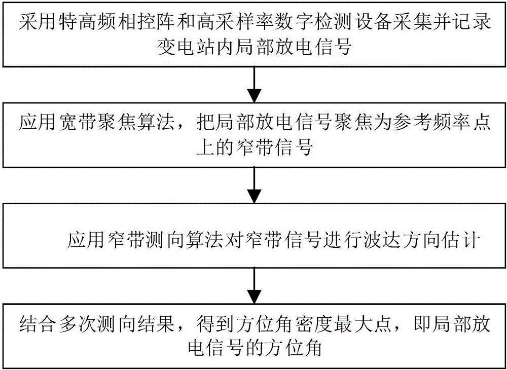
[0052] The specific implementation manner of the present invention will be described below in conjunction with the accompanying drawings and embodiments.

[0053] Such as figure 1 As shown, a partial discharge direction finding method based on the UHF phased array principle in a substation of the present invention includes the following steps:

[0054] 1) UHF phased array and high sampling rate digital detection equipment are used to collect and record partial discharge signals in substations;

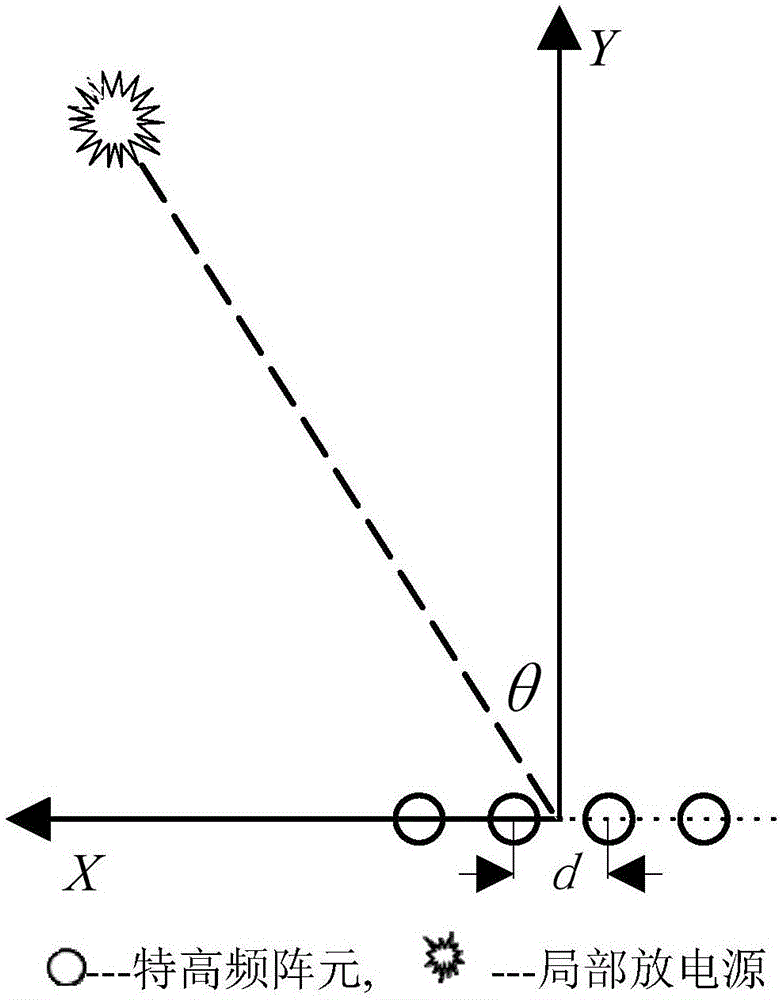
[0055] As an example, figure 2 The model of the uniform linear UHF phased array established for the present invention. Set partial discharge sources at multiple positions, and the azimuth angle θ ranges from -90° to 90° relative to the center of the uniform linear array. Set the azimuth angle θ on the left side of the Y axis to be positive, and the azimuth angle θ on the right side to be positive. burden. In the simulation, the azimuth angle of the partial discharge source is set ...


PUM


Abstract

The invention discloses a partial discharge direction finding method based on an ultrahigh-frequency phased array principle in a substation. The method includes following steps: (1) acquiring and recording partial discharge signals in the substation by employing the ultrahigh-frequency phased array and a digital detection device with high sampling rate; (2) focusing the partial discharge signals to form narrowband signals at a reference frequency point by employing a broadband focusing algorithm; (3) performing direction-of-arrival estimation on the narrowband signals by employing a narrowband direction finding algorithm; and (4) obtaining the point with maximum azimuth density with combination of multiple direction-finding results, namely the azimuth of the partial discharge signals. According to the method, the size of the ultrahigh-frequency phased array is small so that tour inspection is facilitated, and the spatial resolution is high; and according to the method, for the partial discharge signals in the substation, the partial discharge signals are converted to the narrowband signals by employing the focusing algorithm, and the azimuth of the partial discharge signals is obtained by employing the direction finding algorithm so that the direction-finding precision is high, and the ability of suppressing noise interference is great.

Description

Technical field: [0001] The invention relates to the field of partial discharge detection, in particular to a partial discharge direction finding method based on the UHF phased array principle in a substation. Background technique: [0002] Partial discharge is not only the main cause of insulation failure of power equipment, but also an important symptom and detection method of insulation defects. At present, the partial discharge detection based on ultra-high frequency technology carried out at home and abroad usually installs the sensor on specific single equipment such as gas-insulated combined electrical equipment and transformers. The partial discharge detection and direction finding of substation equipment are mainly for specific equipment, and all power equipment in the substation may have partial discharge. If a partial discharge monitoring system is installed on secondary equipment such as bushings and circuit breakers, the cost is extremely high and the maintenanc...

Claims


Application Information

Patent Timeline
IPC IPC(8): G01R31/12
CPCG01R31/1227
Inventor 邓军波刘青朱明晓王彦博张冠军
Owner XI AN JIAOTONG UNIV
Why Eureka
Try Eureka