Self-biasing phase-locked loop

A phase-locked loop and self-bias technology, which is applied in the automatic control of power, electrical components, etc., can solve the problems of poor loop stability and achieve good loop stability performance

Active Publication Date: 2017-04-05
SEMICON MFG INT (SHANGHAI) CORP +1
View PDF7 Cites 7 Cited by
  • Summary
  • Abstract
  • Description
  • Claims
  • Application Information

AI Technical Summary

Problems solved by technology

[0004] A technical problem to be solved by the present invention is: the loop parameter variable of the phase-

Method used


Image

  • Self-biasing phase-locked loop
  • Self-biasing phase-locked loop
  • Self-biasing phase-locked loop

Examples


Embodiment Construction

[0027] Various exemplary embodiments of the present invention will now be described in detail with reference to the accompanying drawings. It should be noted that the relative arrangements of components and steps, numerical expressions and numerical values ​​set forth in these embodiments do not limit the scope of the present invention unless specifically stated otherwise.

[0028] At the same time, it should be understood that, for the convenience of description, the sizes of the various parts shown in the drawings are not drawn according to the actual proportional relationship.

[0029] The following description of at least one exemplary embodiment is merely illustrative in nature and in no way taken as limiting the invention, its application or uses.

[0030] Techniques, methods and devices known to those of ordinary skill in the relevant art may not be discussed in detail, but where appropriate, such techniques, methods and devices should be considered part of the Authorized...


PUM


Abstract

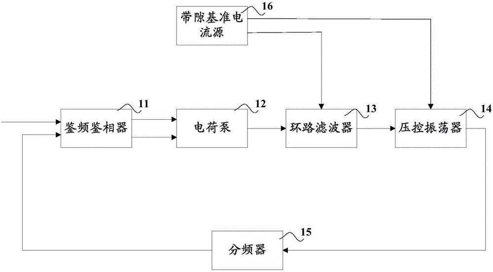
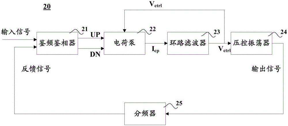
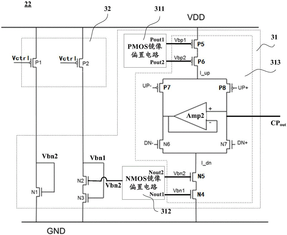
The invention discloses a self-biasing phase-locked loop. The self-biasing phase-locked loop comprises a phase frequency detector, a charge pump, a loop filter, a voltage controlled oscillator and a frequency divider. The charge pump can receive control voltage from the loop filter and adjust charging or discharging current to be in the linear relationship with the control voltage. The voltage controlled oscillator can generate an output signal according to the inputted control voltage and adjust the frequency of the output signal to be proportional to the control voltage. According to the self-biasing phase-locked loop, the charging or discharging current of the charge pump is adjusted to be in the linear relationship with the control voltage, and the frequency of the output signal of the voltage controlled oscillator is adjusted to be proportional to the control voltage so that the open loop gain, the loop closed damping factor and the natural attenuation frequency of the phase-locked loop are enabled not to change along with the change of the frequency, and the self-biasing phase-locked loop is enabled to have great loop stability.

Description

technical field [0001] The invention relates to the technical field of semiconductors, in particular to a self-biased phase-locked loop. Background technique [0002] Phase-locked loop (Phase-locked Loop, PLL) as a main clock signal generation module is widely used in processor chips (microprocessors), input and output interface chips (I / O interfaces), wireless communication chips, and various SoCs (system-on-chip, SOC). In recent years, with the rapid popularization of miniaturized and low-power devices such as the Internet of Things, wearable devices, and medical electronic sensors, electronic devices have put forward higher and higher requirements for low power consumption and small size of the phase-locked loop module in the system. Performance requirements such as the phase jitter (Phase Jitter) of the output clock must also meet the corresponding specifications. All of the above are very challenging tasks for the circuit realization of the phase-locked loop, especial...

Claims


Application Information

Patent Timeline
IPC IPC(8): H03L7/099
CPCH03L7/0896H03L7/0898H03L7/0995H03L7/104H03L7/0891H03L7/099H03L7/093
Inventor 贾海珑
Owner SEMICON MFG INT (SHANGHAI) CORP
Why Eureka
Try Eureka