Piezoelectric drive amplification mechanism and its design method for micro flapping rotor aircraft

A technology of amplifying mechanism and piezoelectric drive, applied in aircraft, design optimization/simulation, CAD based on constraints, etc., can solve the problems of small output displacement of piezoelectric drive, large space volume, small magnification, etc., to achieve small size, The structure is simple and the effect of improving space utilization

Active Publication Date: 2019-04-05
BEIJING INSTITUTE OF TECHNOLOGYGY
View PDF5 Cites 0 Cited by
  • Summary
  • Abstract
  • Description
  • Claims
  • Application Information

AI Technical Summary

Problems solved by technology

However, limited by the characteristics of the piezoelectric material itself, the piezoelectric drive has the disadvantage of small output displacement, so a corresponding drive amplification mechanism is required to amplify the generated displacement
[0003] At present, the common piezoelectric drive amplification mechanism has the disadvantages of small magnification and large space volume, and it is difficult to adopt it on the miniature flapping rotor aircraft. Therefore, a drive amplification mechanism with small size, high magnification and good force transmission performance is needed.

Method used


Image

  • Piezoelectric drive amplification mechanism and its design method for micro flapping rotor aircraft
  • Piezoelectric drive amplification mechanism and its design method for micro flapping rotor aircraft
  • Piezoelectric drive amplification mechanism and its design method for micro flapping rotor aircraft

Examples


Embodiment Construction

[0050] The present invention will be described in further detail below in conjunction with the accompanying drawings. This embodiment is implemented on the premise of the technical solution of the present invention, and detailed implementation methods and specific operating procedures are provided, but the protection scope of the present invention is not limited to the following the embodiment.

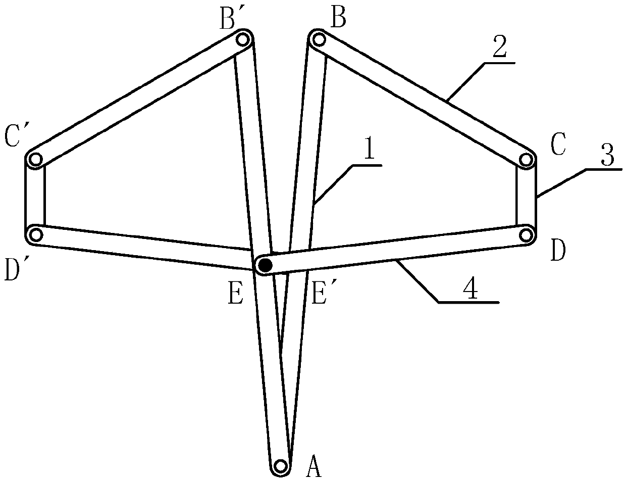
[0051] Such as figure 1 As shown, a piezoelectric drive amplification mechanism for a miniature flapping rotor aircraft is composed of two sets of symmetrical crank-rocker mechanisms ABCDE and A′B′C′D′E′. These two groups of four-bar mechanisms The structure and size of each component are exactly the same. The main components of the mechanism include rockers AB and A′B′, connecting rods BC and B′C′, cranks CD and C′D′, connecting rods DE and D′E′, forming two sets of left and right crank-rocker mechanisms, of which The rocker AB is connected to the connecting rod BC by a smooth hing...


PUM


Abstract

The invention relates to a piezoelectric drive amplifying mechanism for a micro flapping-wing and rotary-wing air vehicle and a design method of the piezoelectric drive amplifying mechanism, and belongs to the field of air vehicle design. According to the piezoelectric drive amplifying mechanism, two sets of crank and rocker mechanisms in bilateral symmetry are used for amplifying micrometric displacement output by a piezoelectric driver into large angular displacement output, and the piezoelectric drive amplifying mechanism has the beneficial effects of being small in space size and simple in structure. Meanwhile, the design method of the piezoelectric drive amplifying mechanism is provided. By means of the method, a piezoelectric drive amplifying mechanism design scheme which has good force transmission performance and meanwhile can complete the designated amplification factor can be obtained. According to the piezoelectric drive amplifying mechanism, symmetric structure design is adopted in the two sets of crank and rocker mechanisms, a rack is formed by rockers on the opposite sides, the space utilization rate is increased, and the piezoelectric drive amplifying mechanism has the beneficial effects of being small in size and simple in structure. The piezoelectric drive amplifying mechanism which can meet and complete output of sufficient-amplitude flapping angles and meanwhile has the good force transmission performance is obtained by building a drive mechanism optimized mathematical model for solution.

Description

technical field [0001] The invention relates to a piezoelectric drive amplification mechanism for a miniature flapping rotor aircraft and a design method thereof, belonging to the field of aircraft design. Background technique [0002] Micro-flapping-rotor aircraft is a new concept aircraft that combines flapping wings and rotors. It expands the traditional bionic flapping-wing motion to flapping and self-propelled rotating motions, and makes full use of the high aerodynamic efficiency of bionic flapping wings at low Reynolds numbers. It has the characteristics of high mechanical efficiency when it is in continuous rotation with the artificial mechanism, and has a very good development prospect. Due to its simple structure, fast response, and high power density, piezoelectric drive is an ideal drive method for micro flapping rotorcraft. However, limited by the characteristics of the piezoelectric material itself, the piezoelectric drive has the disadvantage of small output ...

Claims


Application Information

Patent Timeline
Patent Type & Authority Patents(China)
IPC IPC(8): B64C33/02G06F17/50
CPCB64C33/02G06F30/15G06F30/20G06F2111/04
Inventor 贺媛媛陶志坚崔颖苏醒曹博远
Owner BEIJING INSTITUTE OF TECHNOLOGYGY
Why Eureka
Try Eureka