A Cold Cathode Compact Amplifier

A technology of cold cathode and amplifier, which is applied in the direction of the cathode, discharge tube, and time-of-flight electron tube of the time-of-flight electron tube. Effects of reduced volume, reduced number of cycles, reduced volume and device processing difficulty

Active Publication Date: 2019-07-23
UNIV OF ELECTRONICS SCI & TECH OF CHINA
View PDF0 Cites 0 Cited by
  • Summary
  • Abstract
  • Description
  • Claims
  • Application Information

AI Technical Summary

Problems solved by technology

[0003] Traditional vacuum devices generally use hot cathodes, which have the disadvantages of large volume, low work efficiency, slow reaction speed, and easy damage
[0004] Compared with the hot cathode electric vacuum radiation source, the solid-state semiconductor radiation source device has the advantages of small size, integration, and fast response speed, but it has the disadvantages of weak anti-interference, radiation resistance, and low power, especially in the space environment. The reliability of solid-state radiation source devices is difficult to guarantee

Method used


Image

  • A Cold Cathode Compact Amplifier
  • A Cold Cathode Compact Amplifier
  • A Cold Cathode Compact Amplifier

Examples


Embodiment Construction

[0047] The cold cathode compact amplifier of the present invention will be described in detail below with reference to the accompanying drawings.

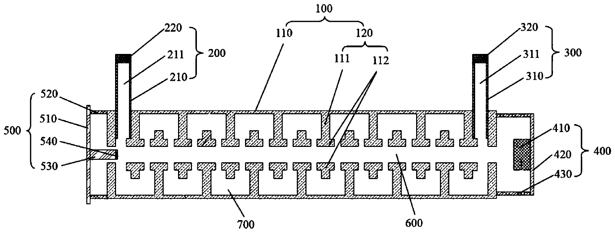
[0048] Such as figure 1 , figure 2 As shown, a cold cathode compact amplifier includes a high frequency interaction system 100 , an input structure 200 , an output structure 300 , a collector 400 and a cold cathode electron gun 500 .

[0049] Preferably, the high frequency interaction system 100 , the input structure 200 , the output structure 300 , the collector 400 and the cold cathode electron gun 500 are hermetically connected by welding.

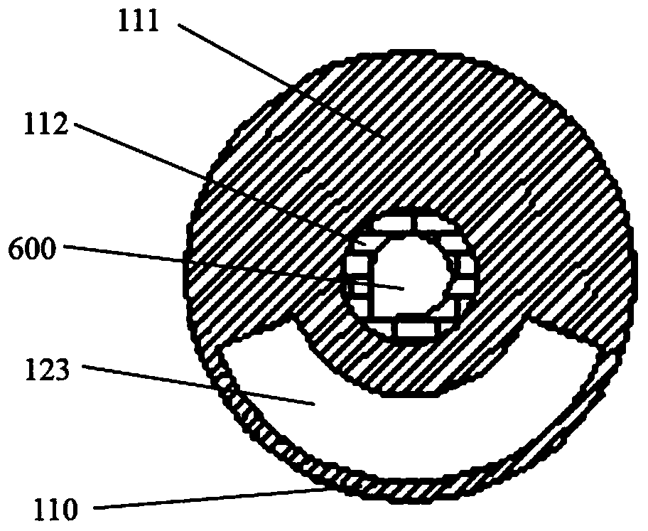
[0050] The high frequency interaction system 100 includes a housing 110 and a periodic slow wave structure 120 disposed in the housing 110 .

[0051] Preferably, the housing 110 may be a circular tube or a square tube, so that a cavity is formed in the housing 110 .

[0052] Preferably, the periodic slow-wave structure 120 is a Hughes coupling cavity slow-wave structure, a linearly arran...


PUM


Abstract

The present invention relates to a cold cathode compact amplifier. It includes a high-frequency interaction system, an input structure, an output structure, a collector and a cold cathode electron gun; the high-frequency interaction system includes a shell and a periodic slow-wave structure; one end of the shell is sealed with the cold cathode electron gun, and the other end is connected with the collector Extremely sealed connection; the input structure is hermetically connected to the shell in a way of penetrating the shell, and the input structure is arranged on the end of the shell close to the cold cathode electron gun; on the end close to the collector. By using the cold cathode electron gun as the electron source, with the periodic slow-wave structure, the high-frequency field is used to modulate the density of the electron injection. The modulated electron injection enters the high-frequency interaction system and interacts with the high-frequency electromagnetic field, exchanging energy and realizing the signal. Therefore, the number of cycles of the periodic structure is greatly reduced, and the volume of the electric vacuum amplifying device and the processing difficulty of the device are reduced.

Description

technical field [0001] The invention belongs to the technical field of electric vacuum devices in microwave, millimeter wave, submillimeter wave and terahertz frequency bands, and relates to an amplifier, in particular to a cold cathode compact amplifier. Background technique [0002] Microwave, millimeter wave, submillimeter wave, and terahertz electric vacuum devices have been widely valued as indispensable core devices for military electronic systems such as radar, electronic countermeasures, and space communications. [0003] Traditional vacuum devices generally use hot cathodes, which have the disadvantages of large volume, low work efficiency, slow reaction speed, and easy damage. [0004] Compared with the hot cathode electric vacuum radiation source, the solid-state semiconductor radiation source device has the advantages of small size, integration, and fast response speed, but it has the disadvantages of weak anti-interference, radiation resistance, and low power, e...

Claims


Application Information

Patent Timeline
Patent Type & Authority Patents(China)
IPC IPC(8): H01J23/04H01J23/00H01J23/24H01J23/26
Inventor 袁学松钟俊男鄢扬李海龙王彬
Owner UNIV OF ELECTRONICS SCI & TECH OF CHINA
Why Eureka
Try Eureka