Fishbone-shaped anchor rod

An anchor rod and fishbone technology, which is used in the installation of anchor rods, sheet pile walls, mining equipment, etc., can solve the problems of insufficient pull-out resistance, small anchoring depth, and corrosion of anchors, so as to improve durability and reduce Frictional resistance, the effect of improving self-supporting capacity

Inactive Publication Date: 2017-04-19
HEFEI UNIV OF TECH
View PDF8 Cites 46 Cited by
  • Summary
  • Abstract
  • Description
  • Claims
  • Application Information

AI Technical Summary

Problems solved by technology

[0005] In order to overcome the disadvantages of existing anchors such as construction difficulties, small anchoring depth, insufficient pull-out re

Method used


Image

  • Fishbone-shaped anchor rod
  • Fishbone-shaped anchor rod
  • Fishbone-shaped anchor rod

Examples


Embodiment Construction

[0041] The present invention will be further described through the embodiments below in conjunction with the accompanying drawings.

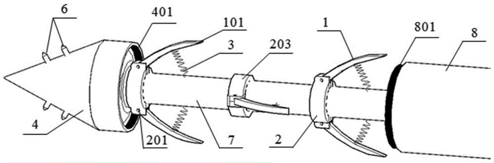
[0042] see figure 1 , a herringbone anchor rod includes an anchor head 4, an anchor rod 7 and a sleeve tube 8; the anchor head 4 is equipped with a movable conical propulsion body 5, and the propulsion body 5 is connected to the anchor rod 7 through the external thread 701 of the anchor rod Front end, the front portion of anchor rod 7 is evenly distributed with grouting holes 702, see Figure 7 ; The anchor head 4 is connected to the front end of the sleeve pipe 8 through the cooperation of the anchor head internal thread 401 and the sleeve pipe external thread 801 .

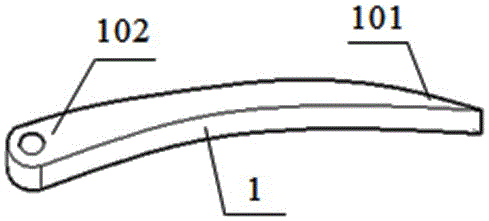
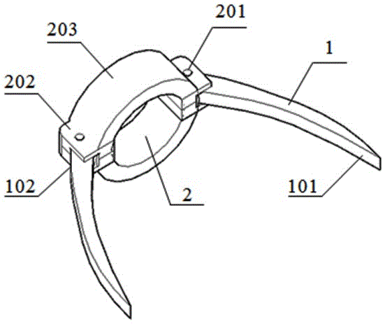
[0043] Two pairs of fishbone-shaped blade mechanisms are evenly distributed on the anchor rod 7 , and the blade mechanisms include blades 1 and clamps 2 . Two pairs of blades are arranged in a staggered manner on the anchor rod 7, and the distance between two adjacent pairs of b...


PUM


Abstract

The invention relates to a fishbone-shaped anchor rod. The fishbone-shaped anchor rod comprises an anchor head, an anchor rod body and a sleeve pipe. A movable conical propelling body is arranged in the anchor head and connected to the front end of the anchor rod body through a thread. The anchor head is connected to the front end of the sleeve pipe through a thread. Spine holes are evenly distributed in the anchor head and internally provided with short-rod-shaped anchor head bore spines. Two or more pairs of fishbone-shaped blade mechanisms are evenly distributed on the anchor rod body. Each blade mechanism comprises blades and a clamp. When the fishbone-shaped anchor rod is not used, the blades are folded, abut against the anchor rod body and are located in the sleeve pipe. When the fishbone-shaped anchor rod is used, a roof bolter rotates forwards, and the fishbone-shaped anchor rod is drilled into rock soil. Pressure is exerted on the rear end of the anchor rod body, the propelling body in the anchor head extrudes the anchor head bore spines out of the anchor head, and the anchor head bore spines are embedded in a rock soil body. The roof bolter rotates reversely till the sleeve pipe is separated from the anchor head. Then, outward pull force is provided for the anchor rod body till the blades evenly distributed on the anchor rod body are in a completely unfolded state. Finally, a grouting machine is aligned with the anchor rod body and pours cement paste into the anchor rod body till a cavity between the anchor rod body and the rock soil body is completely filled. Then, installation of the anchor rod body is finished.

Description

technical field [0001] The invention relates to the technical field of rock and soil reinforcement, in particular to an anchor for rock and soil reinforcement. Background technique [0002] Anchor is a bar system structure for rock and soil reinforcement. Through the longitudinal tension of the anchor rod body, it overcomes the shortcoming that the tensile capacity of rock and soil is far lower than the compressive capacity, increases the cohesion of rock and soil, and achieves effect on rock stabilization. [0003] Existing anchor rods are of a great variety, but most of them have insufficient commonality. Due to the force of the external environment, when there is relative sliding between the rock and soil mass and the anchor, the deformation adaptability of the anchor is poor, resulting in weakened anchoring capacity and loss of its original ability, which ultimately affects the safety of the project. Most of the bolts use the extrusion between the anchoring device and ...

Claims


Application Information

Patent Timeline
IPC IPC(8): E02D5/74E21D21/00E21D20/02
CPCE02D5/74E21D20/02E21D21/00E21D21/0033E21D21/0046
Inventor 王志亮毕程程
Owner HEFEI UNIV OF TECH
Why Eureka
Try Eureka