Double-compression three-way copper tube and forming method thereof

A tee, copper tube technology, applied in the direction of pipes, branch lines, pipes/pipe joints/pipes, etc., can solve the problems of high welding process requirements, high cost, high defect rate, and reduce product defect rate, reduce The effect of manufacturing cost

Pending Publication Date: 2017-04-19
广东思豪内高压科技有限公司
View PDF8 Cites 5 Cited by
  • Summary
  • Abstract
  • Description
  • Claims
  • Application Information

AI Technical Summary

Problems solved by technology

Complex plumbing requires many copper tee connections such as figure 1 Shown is a double clamping type three-way copper tube. The general processing method of this three-way copper tube is to form a copper tube on the outside of the two-way copper tube by welding, that is, the current three-way copper tube copper pipe in figure 1 There are welds in the middle E. Due to the special requirements of the product use, the welding process is highly required. After welding, it needs to be ground and polished, and the defect rate is high, which will result in higher costs for mass processing.

Method used


Image

  • Double-compression three-way copper tube and forming method thereof
  • Double-compression three-way copper tube and forming method thereof
  • Double-compression three-way copper tube and forming method thereof

Examples


Embodiment Construction

[0021] Embodiments of the present invention will be described in detail below in conjunction with the accompanying drawings.

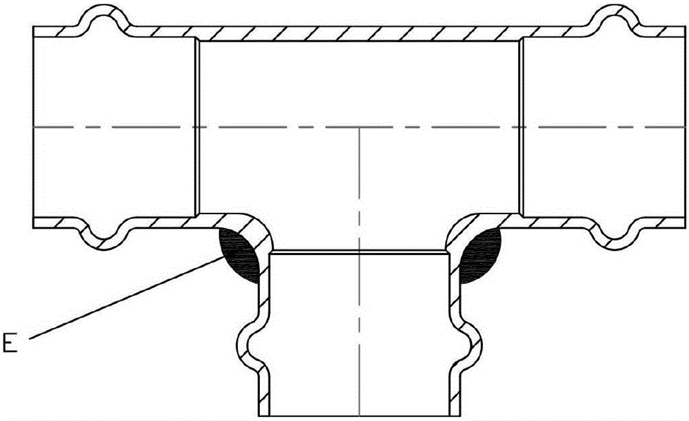
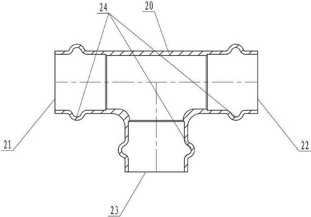
[0022] Such as figure 2 Shown is the double clamping three-way copper pipe of the present invention, the three-way main body 20, the main body 20 is provided with the first interface 21, the second interface 22, the third interface 23, the first interface 21, the second interface 22, the third interface The inner wall of the interface 23 is provided with an annular groove 24, and the inner diameters of the first interface 21, the second interface 22, and the third interface 23 are respectively larger than the inner diameter of the main body 20, and the first interface 21, the second interface 22, and the third interface 23 are connected to the main body. 20 have no welds.

[0023] Such as figure 2 , image 3 , Figure 4 , Figure 5 , Figure 6 , Figure 7 Shown, the forming method step of the present invention's double clamping tee copper pipe...


PUM


Abstract

The invention discloses a double-compression three-way copper tube and a forming method of the double-compression three-way copper tube. The double-compression three-way copper tube comprises a three-way body. The three-way body is provided with a first connector, a second connector and a third connector, wherein no welding joint exists between the first connector and the three-way body, between the second connector and the three-way body and between the third connector and the three-way body. The forming method of the double-compression three-way copper tube comprises the steps that a straightway copper tube blank is placed in the middle of a round hole of a forming mold I, the two ends of the straightway copper tube blank are extruded by a left punch pin and a right punch pin, high-pressure water is fed continuously at the same time, copper materials of the straightway copper tube blank flow under the action of the high extruding force and the high water pressure, and a three-way tube is formed in a cavity of the mold I; an opening of a primarily-formed third branch tube of the three-way tube is flattened; and the three-way tube obtained after the opening is flattened is placed in a T-shaped hole of a mold II, the three-way tube is extruded by a left punch pin, a right punch pin and a back punch pin, high-pressure water is continuously fed at the same time, the three-way tube flows under the action of the high extruding force and the high water pressure, and then the double-compression three-way copper tube is formed in a cavity of the mold II. According to the double-compression three-way copper tube and the forming method of the double-compression three-way copper tube, the double-compression three-way copper tube is integrally formed through the water expanding forming technology, and no welding joint exists between the three-way connectors of and the copper tube body of the double-compression three-way copper tube.

Description

technical field [0001] The invention relates to the field of copper pipes in heating and cooling systems, in particular to a double clamping tee copper pipe and a forming method thereof. Background technique [0002] Building heating and cooling systems are mostly connected by copper pipes. Complex plumbing requires many copper tee connections such as figure 1 Shown is a double clamping type three-way copper tube. The general processing method of this three-way copper tube is to form a copper tube on the outside of the two-way copper tube by welding, that is, the current three-way copper tube copper pipe in figure 1 There are welds in the middle E. Due to the special requirements of the product use, the welding process is required to be high. After welding, it needs to be ground and polished, and the defect rate is high, which will result in higher costs for mass processing. Contents of the invention [0003] The problem to be solved by the present invention is to overc...

Claims


Application Information

Patent Timeline
Patent Type & Authority Applications(China)
IPC IPC(8): F16L41/02B21D26/037B21D26/047
CPCF16L41/021B21D26/037B21D26/047
Inventor 周富强
Owner 广东思豪内高压科技有限公司
Why Eureka
Try Eureka