Supercharge Your Innovation With Domain-Expert AI Agents!

High-speed low-loss mixed medium differential transmission signal line structure

A mixed-media, differential transmission technology, applied in the field of communication materials, can solve problems such as insufficient consistency control, unstable conductor center distance, and affecting signal characteristic transmission, etc., to achieve optimal tuning and differential and common mode impedance, large shielding area, The effect of excellent transmission performance

Inactive Publication Date: 2017-04-19
HANGZHOU LEROM WIRE & ELECTRIC APPLIANCE
View PDF4 Cites 0 Cited by
  • Summary
  • Abstract
  • Description
  • Claims
  • Application Information

AI Technical Summary

Problems solved by technology

[0004] 1. The insulation is extruded on a single conductor as a single-ended signal. When the single-ended signal (core wire) is extruded separately, there are differences between the signal lines, and the consistency control is not precise enough. Two single-ended signals are put together through the aluminum foil. The shielding material is used as a carrier for signal transmission. When bound, it will be easily affected by external forces. The core wire is prone to deformation and the center distance of the conductor is unstable, resulting in a sudden change in impedance and affecting the transmission of signal characteristics.
[0005] 2. The specifications are fixed, the center distance is fixed, and cannot be adjusted, and the space is relatively large
[0006] 3. If you want to reduce the size, you must reduce the specification, then the transmission effect will be significantly reduced, and the insertion loss will increase significantly at the same length
[0007] 4. The coupling between the conductor and the shield is large, and the common mode loss increases

Method used


Image

  • High-speed low-loss mixed medium differential transmission signal line structure
  • High-speed low-loss mixed medium differential transmission signal line structure
  • High-speed low-loss mixed medium differential transmission signal line structure

Examples


Embodiment 1

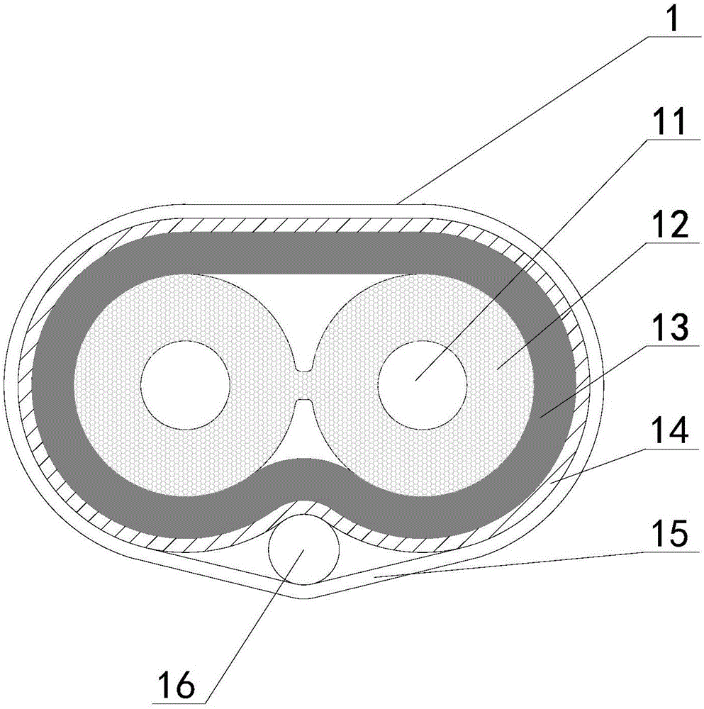
[0021] Such as Figure 1-2 As shown, the high-speed low-loss mixed-medium differential transmission signal line structure includes a main body 1, a conductor 11, a first insulating layer 12, a second insulating layer 13, a shielding layer 14, a mylar layer 15, and a ground wire 16. The first insulating layer The layer 12 wraps the conductor 11 to form a core wire. The two core wires are placed side by side or twisted to each other and are wrapped sequentially through the second insulating layer 13 and the shielding layer 14 to form a wrapping wire, and the first insulating layer of the two core wires 12 is connected as a whole through PE extrusion, and the mylar layer 15 wraps the wrapping wire and the ground wire 16 to form the signal wire structure main body 1; the material of the first insulating layer 12 is Skin-Foam-Skin or HDPE; The second insulating layer 13 is an EPTFE layer, and the EPTFE layer is formed by winding an EPTFE tape, and the winding overlap rate is 50%; t...


PUM


Abstract

The invention discloses a high-speed low-loss mixed medium differential transmission signal line structure which is characterized by comprising a main body, conductors, first insulting layers, a second insulating layer, a shielding layer, a mylar layer and a ground line. The first insulating layers wrap the conductors so as to form core wires. The two core wires are arranged in parallel or mutually twisted and wrapped by the second insulating layer and the shielding layer in turn to form a wrapped line, and the first insulating layers of the two core wires are connected as a whole body through PE extrusion. The beneficial effects of the high-speed low-loss mixed medium differential transmission signal line structure are that the high-speed low-loss mixed medium double coaxial differential transmission signal line is stable in impedance, more excellent in transmission performance and lower in insertion loss so that the transmission distance is longer, the transmission bandwidth can be increased, the physical size of the line can be smaller and the space occupation can be reduced; the larger shielding area can be realized, coupling between the signal line conductors can be increased and coupling between the conductors and shielding can be reduced; and differential and common mode impedance can be better tuned.

Description

technical field [0001] The invention relates to a signal line, in particular to a high-speed and low-loss mixed medium differential transmission signal line structure, belonging to the technical field of communication materials. Background technique [0002] The signal line mainly refers to the line used to transmit sensing information and control information in the electrical control circuit. Signal lines are often composed of multiple cables as one or more bundles of transmission lines, or they can be printed lines arranged in printed circuit boards. With the continuous advancement of technology and applications, signal lines have developed from metal carriers to other Carriers, such as optical cables, etc. Signal lines for different purposes often have different industry standards to facilitate standardized production and application. [0003] Similar signal line products currently on the market have the following disadvantages: [0004] 1. The insulation is extruded o...

Claims


Application Information

Patent Timeline
IPC IPC(8): H01B7/02H01B11/00H01B11/06H01B7/08
CPCH01B7/0216H01B7/0283H01B7/0291H01B7/0807H01B7/0823H01B7/0838H01B7/0861H01B7/0876H01B11/002H01B11/06
Inventor 张军萍石磊许利强
Owner HANGZHOU LEROM WIRE & ELECTRIC APPLIANCE
Features
  • R&D
  • Intellectual Property
  • Life Sciences
  • Materials
  • Tech Scout
  • Unparalleled Data Quality
  • Higher Quality Content
  • 60% Fewer Hallucinations
Learn More