Decoupling method and decoupling network of MIMO antenna of mobile communication system terminal
A mobile communication system and antenna technology, applied in the field of decoupling networks, can solve the problems of being easily affected by the external environment, the difference in antenna efficiency, and the narrow working bandwidth, achieving strong portability and compatibility, simple configuration, and improved isolation. Effect
- Summary
- Abstract
- Description
- Claims
- Application Information
AI Technical Summary
Problems solved by technology
Method used
Image

Examples
Embodiment 1
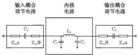
[0022] The decoupling method of the MIMO antenna of the mobile communication system terminal, by inserting an additional coupling resonator between the antenna ports, introduces an equal-amplitude and anti-phase current that cancels out the coupling current, thereby improving the isolation of the dual-antenna system and improving the antenna Radiation efficiency, greatly reducing the spatial correlation of the antenna, and achieving decoupling. The coupling resonator uses an adjustable low-pass filter to realize decoupling.
Embodiment 2
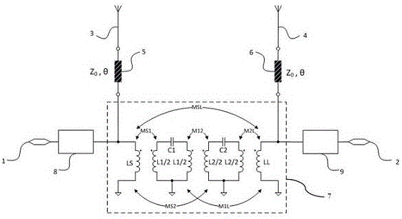
[0024] The decoupling method of the MIMO antenna of the mobile communication system terminal, by inserting an additional coupling resonator between the antenna ports, introduces an equal-amplitude and anti-phase current that cancels out the coupling current, thereby improving the isolation of the dual-antenna system and improving the antenna Radiation efficiency, greatly reducing the spatial correlation of the antenna, and achieving decoupling. The coupling resonant cavity realizes decoupling through two resonant units composed of capacitance and inductance and direct coupling and cross coupling between them.
Embodiment 3
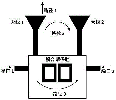
[0026] The decoupling network realized by using the decoupling method of the terminal MIMO antenna of the mobile communication system, such as figure 1 As shown, it includes antenna 1 and port 1 corresponding to antenna 1, antenna 2 and port 2 corresponding to antenna 2, and a coupling resonator; the power fed into port 1 is consumed through three paths: path 1 radiates to free space; Path 2 couples to antenna 2 through free space and causes interference to antenna 2; while the power of path 3 is coupled to antenna 2 through the coupling resonator; the coupling resonator can make the coupling through path 2 and path 3 equal amplitude If the phase is reversed, port 2 will not receive power from port 1, achieving decoupling. In the figure above, the core part is the coupling resonator, and its realization in different forms corresponds to different forms of circuits that solve multi-antenna coupling. Realizing the circuit in the form of an integrated circuit can realize the com...
PUM
 Abstract
Description
Claims
Application Information