
Copper alloy plate strip for use in led lead frame

A technology of copper alloy and lead frame, applied in the direction of metal/alloy conductors, metal layered products, root rods/rods/wires/strip conductors, etc., which can solve the problems of high brightness of LED components approaching the limit and component cost increase, etc. Achieve the effect of improving reflectivity and improving heat release

Inactive Publication Date: 2017-04-19
KOBE STEEL LTD
View PDF8 Cites 6 Cited by
  • Summary
  • Abstract
  • Description
  • Claims
  • Application Information

AI Technical Summary

Problems solved by technology

However, the high brightness of LED components is approaching the limit, and the cost of components will increase significantly if the brightness is only slightly increased.

Method used


Image

  • Copper alloy plate strip for use in led lead frame
  • Copper alloy plate strip for use in led lead frame
  • Copper alloy plate strip for use in led lead frame

Examples


Embodiment 1

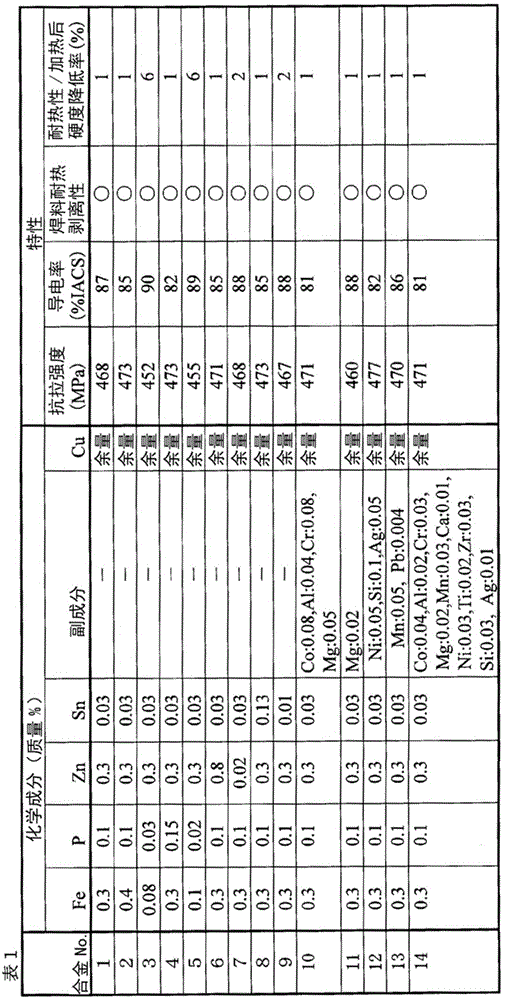
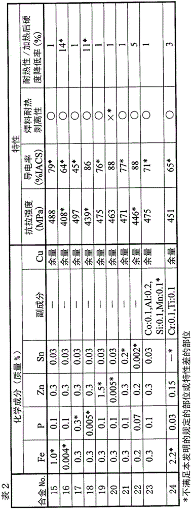
[0045] Copper alloys (alloy Nos. 1 to 24) with the compositions shown in Tables 1 and 2 were melted under a charcoal coating in the atmosphere using a small electric furnace to melt an ingot with a thickness of 50 mm, a width of 80 mm, and a length of 180 mm. The surface and the back surface of the produced ingot were subjected to 5 mm face-cutting, followed by homogenization treatment at 950° C., followed by hot rolling to form a 12 mmt-thick plate, which was quenched. The front and back faces of this board were each face-cut by about 1 mm. For these plates, after repeated cold rolling and precipitation annealing at 500-550°C for 2-5 hours, the final cold-rolling was performed at a processing rate of 40% using a mirror-finished 50mm-diameter saron ceramic roll. A copper alloy strip with a thickness of 0.2mm and a width of 180mm is used as the test material. The lubricating oil described above is used in the finish cold rolling, and the rotational speed and drawing tension of...

Embodiment 2

[0060]Copper alloys (alloy Nos. 1, 2, 3, 10, 15, and 24) with the compositions shown in Tables 1 and 2 were melted in a small electric furnace under a charcoal coating in the atmosphere, and an ingot with a thickness of 50 mm, a width of 80 mm, and a length of 180 mm was melted. . The surface and the back surface of the produced ingot were subjected to 5 mm face-cutting, followed by homogenization treatment at 950° C., followed by hot rolling to form a 12 mmt-thick plate, which was quenched. The front and back faces of this board were each face-cut by about 1 mm. For these plates, after repeated cold rolling and precipitation annealing at 500-550°C for 2-5 hours, the final cold-rolling was performed at a processing rate of 40% using a mirror-finished 50mm-diameter saron ceramic roll. A copper alloy strip with a thickness of 0.2mm and a width of 180mm is used as the test material. In the final cold rolling, adjust the surface roughness of the salen ceramic roll and the rotati...


PUM

PropertyMeasurementUnit
mean roughnessaaaaaaaaaa
surface roughnessaaaaaaaaaa
lengthaaaaaaaaaa

Abstract

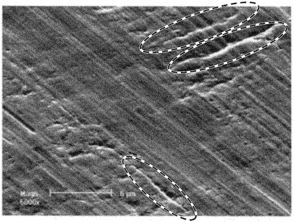
This Cu-Fe-based copper alloy plate strip includes specific amounts of Fe, P, Zn, and Sn, the balance substantially comprising Cu and unavoidable impurities, the surface roughness in the direction perpendicular to the rolling direction thereof having an arithmetic mean roughness Ra of less than 0.06 [mu]m, and a ten-point average roughness RzJIS of less than 0.5 [mu]m. Groove-shaped recesses that are present on the surface and have a length of at least 5 [mu]m and a depth of at least 0.25 [mu]m number two or fewer per 200 [mu]m * 200 [mu]m area, and the thickness of an affected layer on the surface that comprises microscopic crystal grains is 0.5 [mu]m or less.

Description

technical field [0001] The present invention relates to, for example, a copper alloy strip (plate and strip) used as a lead frame of an LED, and an Ag-plated copper alloy strip. Background technique [0002] In recent years, a light emitting device using a light emitting diode (LED: Light Emitting Diode) as a light source has been widely used in a wide range of fields because of its energy saving and long life. LED elements are fixed to a copper alloy lead frame with excellent thermal conductivity and electrical conductivity, and assembled into a package. In order to efficiently extract light emitted from the LED element, an Ag-plated film is formed as a reflective film on the surface of the copper alloy lead frame. Since LED packages are used as lighting and backlights for personal computers, mobile phones, etc., it is necessary to make lighting and screens brighter, and the demand for higher brightness of LED packages is increasing. [0003] In order to increase the brig...

Claims


Application Information

Patent Timeline
Patent Type & Authority Applications(China)
IPC IPC(8): C22C9/00C22C9/01C22C9/02C22C9/04C22C9/05C22C9/06C22C9/10C22F1/08H01B1/02H01B5/02H01L23/48H01L23/50H01L33/62C22F1/00
CPCC22C9/00C22C9/04C22F1/00C22F1/08H01L2924/0002C22C5/06H01L33/62B32B15/018C25F1/00H01B1/026C25D5/627C25D5/10C25D5/617C25D5/611H01L2924/00C22C9/02H01B1/02H01B5/02H01L23/48H01L23/50C23G1/103C25D3/38C25D3/46C25D5/34
Inventor 西村昌泰真砂靖畚野章
Owner KOBE STEEL LTD
Learn More