
Motor control device, motor control method, and motor control system

A technology for a control device and a motor, which is applied in the direction of controlling multiple AC motors, converting irreversible DC power input into AC power output, etc., can solve the problems of large conduction noise, radiated noise, large influence, and inability to become large noise, etc. Achieve the effect of avoiding conducted noise and reducing radiated noise

Active Publication Date: 2019-09-06
PANASONIC INTELLECTUAL PROPERTY MANAGEMENT CO LTD
View PDF4 Cites 0 Cited by
  • Summary
  • Abstract
  • Description
  • Claims
  • Application Information

AI Technical Summary

Problems solved by technology

[0006] However, the noise caused by the switching operation in the inverter as described above has a great influence especially during no rotation (servo lock), low speed rotation, and low torque operation where the switching timings of the phases tend to overlap.
Furthermore, in the conventional method of superimposing the AC superimposed signal on the command signal, there is a problem that the switching timings of the U-phase to W-phase overlap during servo lock, low-speed rotation, and low-torque operation. Cannot be a solution to phenomena that generate loud noise
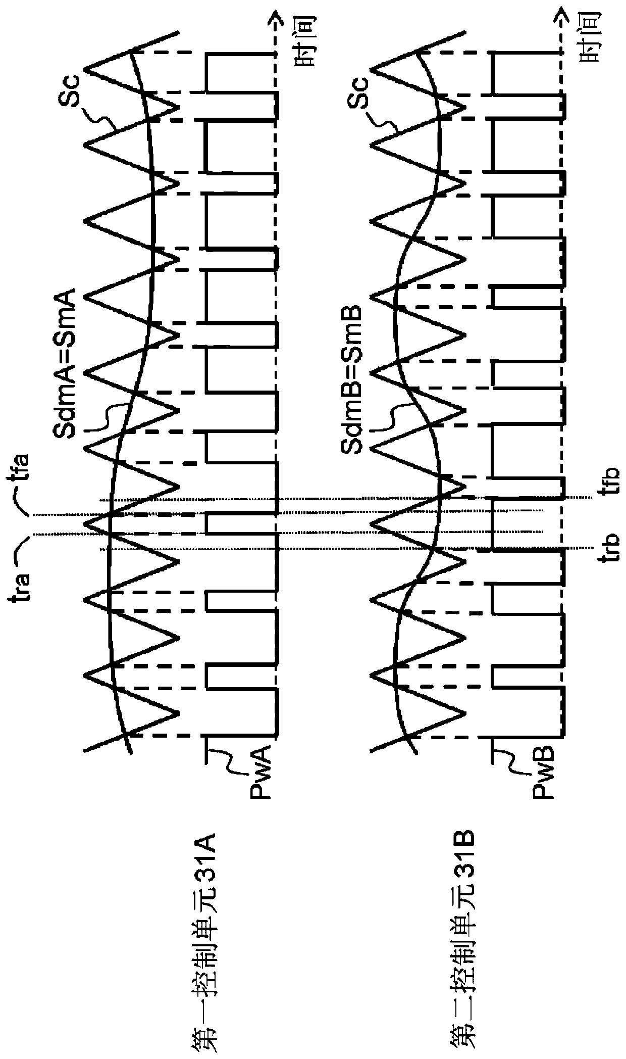
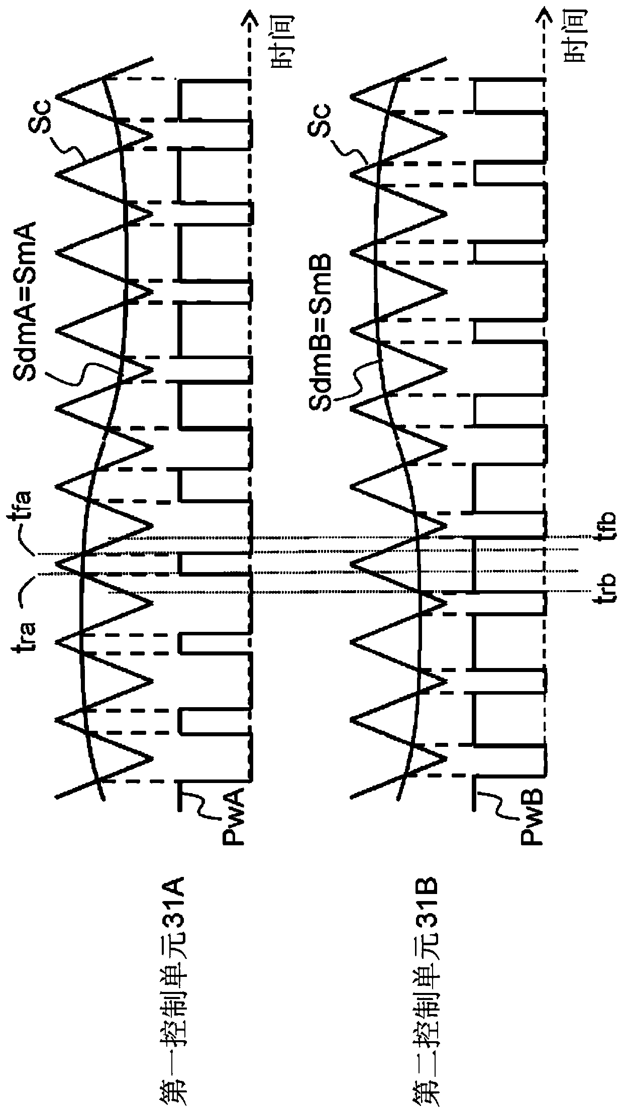
However, if according to Figure 12 As can be clearly seen, the timing of the switching operations of U-phase to W-phase is, for example, Figure 12 Like rising timing tr and falling timing tf in Figure 11 Similarly, overlapping between phases results in large conduction noise and radiation noise at each moment

Method used


Image

  • Motor control device, motor control method, and motor control system
  • Motor control device, motor control method, and motor control system
  • Motor control device, motor control method, and motor control system

Examples


Embodiment approach

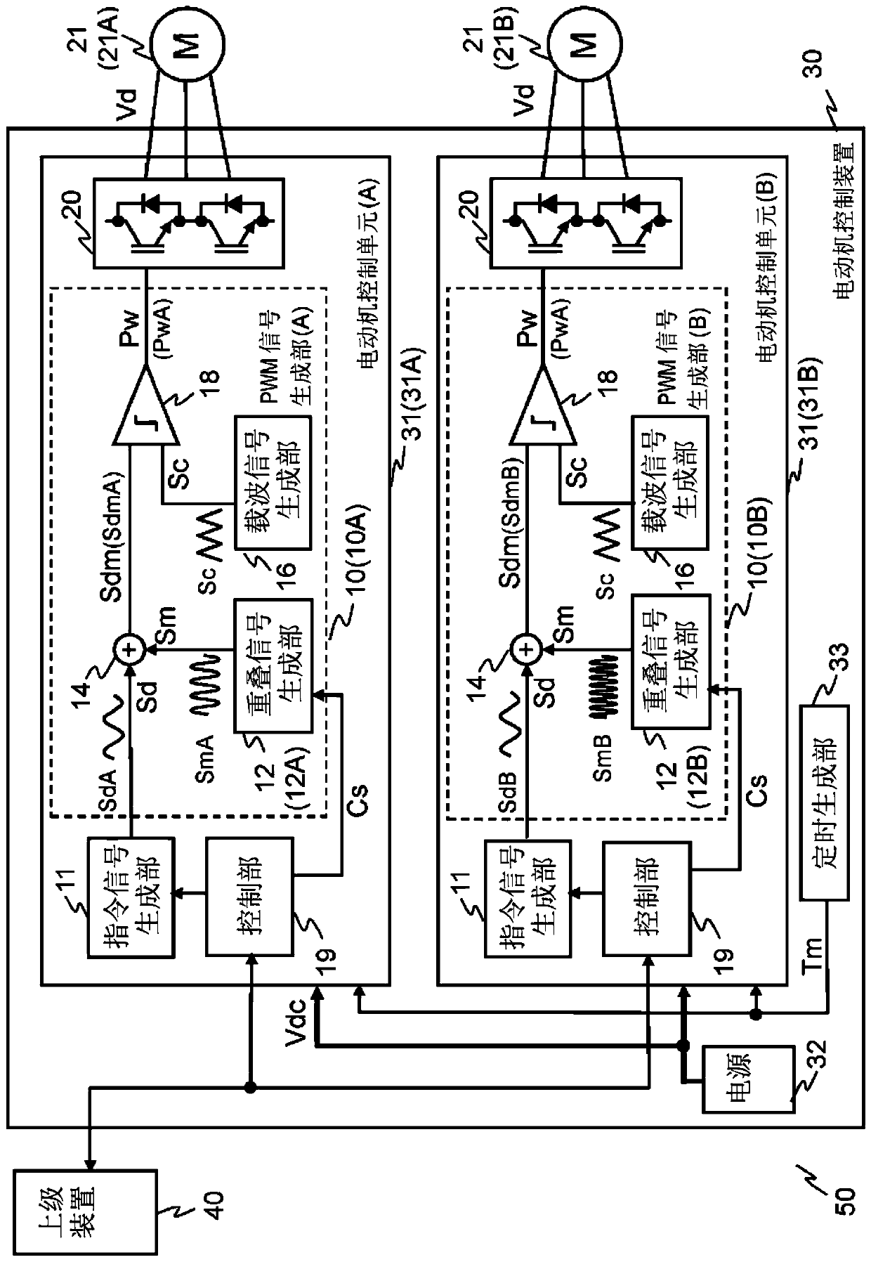
[0030] figure 1 It is a configuration diagram of a motor control system including a motor control device in an embodiment of the present invention. exist figure 1 In the figure, as an example of such a system, the configuration of a motor control system 50 for multi-axis motor control including a motor control device 30 that controls a plurality of motors 21 is shown. Also, as multiple axes, in figure 1 An example including two motors 21 as two shafts is shown in . Furthermore, in order to control the motor control device 30 by commands or the like, the present motor control system 50 also includes a host device 40 using a personal computer or the like, for example. The host device 40 and the motor control device 30 are communicatively connected via a control bus or the like. Commands from the host device 40 are transmitted to the motor control device 30 and information from the motor control device 30 is transmitted to the host device 40 .

[0031] Next, in order to co...


PUM


Abstract

The motor control apparatus according to the present invention has a plurality of motor control units each controlling a shaft on the basis of an operation command from a host apparatus, and synchronizes and controls two or more motor shafts. Each of the motor control units is provided with: a control unit for controlling the operation of a motor; a command-signal generating unit for generating a command signal; a PWM-signal generating unit for generating a PWM control signal in which the pulse-width thereof is modulated on the basis of the command signal; and an inverter for generating a driving signal by switching a switching element using the PWM control signal. Also, each of the PWM-signal generating units is provided with: a superimposing-signal generating unit for generating a superimposing signal to be superimposed on the command signal; a carrier-signal generating unit for generating a carrier signal, which is a triangular wave; an adding unit for adding the command signal and the superimposing signal; and a comparing unit for comparing the superimposed command signal output from the adding unit with the carrier signal to generate a PWM control signal. The superimposing signals are signals that are different for each of the shafts controlled by the plurality of motor control units.

Description

technical field [0001] The present invention relates to a motor control device, a motor control method, and a motor control system for synchronously controlling a plurality of shafts by applying a voltage for PWM control to windings of a motor, and in particular to a motor control system with A motor control device, a motor control method, and a motor control system with a function of controlling the timing of switching operations of an inverter. Background technique [0002] In the servo motor used in FA (FACTORY AUTOMATION: factory automation), the position, speed, and torque of the motor are controlled so that the position, speed, and torque of the motor follow the drive command from the upper device (superior controller) (position command). And, as the control calculation device, digital control using a microcomputer is widely used. In the PWM (PULSE WIDTH MODULATION: Pulse Width Modulation) control method generally used to control the torque of the motor, the current ...

Claims


Application Information

Patent Timeline
Patent Type & Authority Patents(China)
IPC IPC(8): H02P5/74H02M7/48
Inventor 市川英章岸部太郎增田隆宏大音久志
Owner PANASONIC INTELLECTUAL PROPERTY MANAGEMENT CO LTD
Learn More