Complex pipe cavity part reverse flushing equipment and reverse flushing process thereof

A technology of backwashing and complex tubes, applied in the field of parts cleaning, can solve the problems of inability to meet backwashing requirements, limited backwashable parts, low backwashing efficiency, etc., and achieve low noise, high backwashing efficiency, and high safety factor Effect

Active Publication Date: 2017-04-26
CHINA HANGFA GUIZHOU LIYANG AVIATION POWER CO LTD
View PDF5 Cites 3 Cited by
  • Summary
  • Abstract
  • Description
  • Claims
  • Application Information

AI Technical Summary

Problems solved by technology

However, the equipment used in this backwashing process occupies a large area, the operation is troublesome, the noise is large, the parts that can be backwashed are limited, the backwashing efficiency is low, and the safety factor is small.
With the development of the engine, the size of the afterburner fuel manifold has been increasing, and the existing backwashing process and equipment used can no longer meet the backwashing requirements

Method used


Image

  • Complex pipe cavity part reverse flushing equipment and reverse flushing process thereof

Examples


Embodiment Construction

[0024] The technical solution of the present invention is further described below in conjunction with the accompanying drawings, but the scope of protection is not limited to the description.

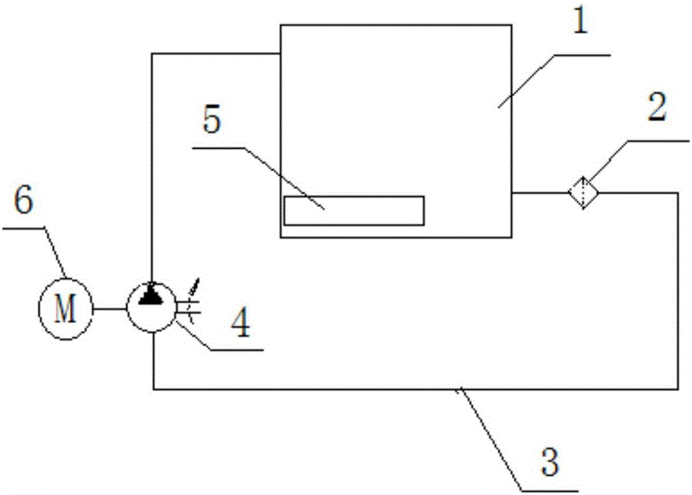
[0025] Such as figure 1 As shown, a backwashing device for complex lumen parts of the present invention includes an open container 1, a gear pump 4 and a motor 6, the motor 6 is connected to the gear pump 6, and the open container 1 and the gear pump 4 They are connected by an oil outlet pipeline 3 , and an ultrasonic generator 5 is installed in the open container 1 . This technical solution adopts the ultrasonic generator 5 arranged in the open container 1, so that the backwash container and the oil collection tank are integrated, which greatly saves space; when backwashing, only the parts need to be immersed in the fuel oil in the open container 1, and then the parts It is connected with the oil outlet pipeline 3, and the gear pump 4 can be started for backwashing, which is easy and ...


PUM


Abstract

The invention discloses complex pipe cavity part reverse flushing equipment and a reverse flushing process. The reverse flushing equipment comprises an opening container, a gear pump and a motor; the motor is connected with the gear pump; the opening container and the gear pump are connected through an oil outlet pipe; a ultrasonic generator is mounted in the opening container; and the oil outlet pipe is provided with a filter at an outlet end of the opening container. The reverse flushing process comprises the following steps; the reverse flushing equipment and the reverse flushing process guarantee the cleanness of inner cavities of parts; the reverse flushing process can satisfy the reverse flushing requirements of any complex pipe cavity parts, and is simple and flexible in operation, high in efficiency, excellent in reverse flushing effect and high in safety coefficient; as a reverse flushing container and an oil collecting tank are integrated, the floor area is small, and the space is saved; and as the gear pump is used, the reverse flushing equipment is low in noise during working.

Description

technical field [0001] The invention belongs to the technical field of parts cleaning, and in particular relates to backwashing equipment and a backwashing process for complex lumen parts. Background technique [0002] Afterburner fuel manifold is a typical complex lumen part on aircraft engine. The main feature of the afterburner fuel oil main pipe is that two or more types of spray rods are welded on a circle of pipes by argon arc welding, and an oil inlet nozzle is welded on the pipes. Taking the pipe as the boundary, the inside of the pipe is called the inner ring spray boom, and the outside of the pipe is called the outer ring spray boom. The number of inner and outer ring spray booms is generally 24, and they are evenly distributed on the circumference of the pipe. There are many small injection holes. The main function of the afterburner fuel manifold is to supply the combustion source to the afterburner and increase the thrust of the engine in a short period of tim...

Claims


Application Information

Patent Timeline
Patent Type & Authority Applications(China)
IPC IPC(8): B08B3/12B08B13/00
CPCB08B3/12B08B3/14B08B9/032B08B13/00
Inventor 黄绍奇赵勇吕开怡梁小龙
Owner CHINA HANGFA GUIZHOU LIYANG AVIATION POWER CO LTD
Why Eureka
Try Eureka