An automatic transition system for sheet metal processing blanking to forming

A blanking and sheet metal technology, applied in the field of sheet metal processing blanking to forming automatic transition system, can solve the problems of unfavorable standardization of mechanical processing operations, unfavorable quality control level, and prone to work-related accidents, so as to reduce the occurrence of work-related accidents Probability, improvement of quality control level, and improvement of operating efficiency

Active Publication Date: 2019-02-15
WUHU YUANSHAN MACHINERY MFG CO LTD
View PDF7 Cites 0 Cited by
  • Summary
  • Abstract
  • Description
  • Claims
  • Application Information

AI Technical Summary

Problems solved by technology

The operation method of manually grabbing the blanking sheet for unloading and transporting it to the subsequent process is not only labor-intensive but also low in efficiency. In addition, work-related accidents are prone to occur. Again, the manual operation method is not conducive to the standardization of mechanical processing operations, thus not It is conducive to improving the quality control level; in addition, the operation method of manually grabbing the blanking sheet and feeding it into the forming or punching die is not conducive to accurately controlling the placement position of the blanking sheet, and it is easy to cause position errors in stamping or punching processing; for Therefore, it is necessary to design an automatic pick-up device for machining station conversion, which can realize the automatic operation of grasping and unloading of blanking plates, station conversion feeding, and forming or punching feeding, so as to overcome the above problems

Method used


Image

  • An automatic transition system for sheet metal processing blanking to forming
  • An automatic transition system for sheet metal processing blanking to forming
  • An automatic transition system for sheet metal processing blanking to forming

Examples


Embodiment Construction

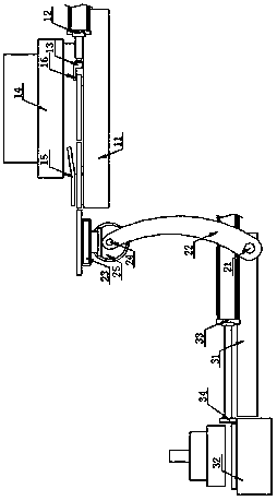
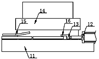
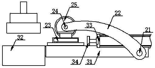
[0019] refer to Figure 1 to Figure 3 , Figure 1 to Figure 3 It is a structural schematic diagram of a specific embodiment of the present invention.

[0020] Such as Figure 1 to Figure 3 As shown, an automatic transition system for sheet metal processing blanking to forming, including a stamping and blanking mechanism, a transfer manipulator and a stamping and forming mechanism arranged sequentially from the upstream end to the downstream end; the stamping and blanking mechanism includes a stamping and blanking lower die Seat 11 and blanking push cylinder 12, the transfer manipulator includes a rotary drive shaft 21, a rotary pick-up swing arm 22 and an electromagnetic pick-up sucker 23, and the stamping and forming mechanism includes a forming feeding platform 31, a stamping and forming lower mold 32 and Forming feeding cylinder 33; the downstream end of the stamping and blanking lower die base 11 is located above the upstream end of the forming feeding platform 31, and t...


PUM


Abstract

The invention discloses an automatic transition system for converting blanking to forming in sheet-metal working. The automatic transition system comprises a punching blanking mechanism, a transfer mechanical arm and a punching forming mechanism which are sequentially arranged from the upstream end to the downstream end. The punching blanking mechanism comprises a punching blanking lower die base and a blanking pushing cylinder. The transfer mechanical arm comprises a rotary driving spindle, a rotary piece-collecting swing arm and an electromagnetic piece-collecting suction cup. The punching forming mechanism comprises a forming feeding platform, a punching forming lower die and a forming feeding cylinder. The downstream end of the punching blanking lower die base is located above the upstream end of the forming feeding platform. The rotary driving spindle is arranged at the upstream end of the forming feeding platform. The downstream end of the forming feeding platform is connected with the punching forming lower die, and the top surface of the forming feeding platform and the top surface of the punching forming lower die are horizontally coplanar. By the adoption of the automatic transition system, automatic operations of grabbing discharge, station transfer feeding and forming or punching feeding of blanked sheets can be realized.

Description

technical field [0001] The invention relates to the technical field of mechanical processing equipment, in particular to an automatic transition system for sheet metal processing blanking to forming. Background technique [0002] Sheet metal parts are processed from raw materials to finished products, usually including blanking, punching, rough forming, finishing and welding. After the blanking process is completed, the blanking sheet is usually picked up manually for unloading, and the unloaded blanking sheet is stacked on the floor plate or a transfer vehicle, and then transported to the subsequent process and sent to the stamping press. Subsequent punching or forming operations are carried out in the mold, and the subsequent punching or forming operations are usually transported by manpower, and the blanking sheet is manually sent into the stamping or punching mold for stamping operations. The operation method of manually grabbing the blanking sheet for unloading and tra...

Claims


Application Information

Patent Timeline
Patent Type & Authority Patents(China)
IPC IPC(8): B21D35/00B21D43/18
CPCB21D35/001B21D35/002B21D43/18
Inventor 徐杨徐克郎
Owner WUHU YUANSHAN MACHINERY MFG CO LTD
Why Eureka
Try Eureka