Petroleum drilling winch

A technology for oil drilling and winch, applied in the direction of hoisting device, spring mechanism, etc., can solve the problems of poor safety, large device volume, complicated braking, etc., and achieve the effect of simple brake, simplified overall structure and improved safety.

Inactive Publication Date: 2017-04-26
BC P INC CHINA NAT PETROLEUM CORP +2
View PDF9 Cites 8 Cited by
  • Summary
  • Abstract
  • Description
  • Claims
  • Application Information

AI Technical Summary

Problems solved by technology

[0004] The purpose of the present invention is to provide an oil drilling winch, which overcomes the problems of large device size, complicated braking and poor safety in the prior art, and realizes the purpose of simplifying the overall structure, simple braking and high safety

Method used


Image

  • Petroleum drilling winch
  • Petroleum drilling winch
  • Petroleum drilling winch

Examples


Embodiment Construction

[0035] In order to have a clearer understanding of the technical features, purposes and effects of the present invention, the specific implementation manners of the present invention will now be described with reference to the accompanying drawings.

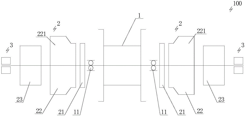
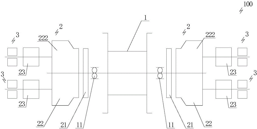
[0036] Such as Figure 1 to Figure 4 As shown, the oil drilling drawworks 100 provided by the present invention includes a drum 1. In this embodiment, a central shaft is pierced in the drum 1 in the axial direction, and bearing seats 11 fixed at the bottom are respectively arranged on both sides of the drum 1. The two ends of the shaft located on the outer side of the drum 1 rotate respectively through the bearing seats 11 on both sides, and the bearing seats 11 on both sides provide rotational support for the drum 1; Both sides are symmetrically connected with a power unit 2 and a brake 3 sequentially from near to far. The power unit 2 on both sides can be turned on and rotated synchronously, and the brakes 3 on both sides can b...


PUM


Abstract

The invention discloses a petroleum drilling winch. The petroleum drilling winch comprises a roller; two sides of the roller are symmetrically connected with power devices and brakes in sequence from near to far; each power device is connected with the roller through a clutch, and includes a transmission; one ends of the transmissions are connected with the clutches, and the other ends of the transmissions are connected with driving motors; the driving motors are alternating-current variable frequency motors with two discharge ends; and the other ends of the driving motors are connected with the brakes. The petroleum drilling winch overcomes such problems as large device size, complex braking and weak safety in the prior art, and realizes the purposes of simple overall structure, simple braking and high safety.

Description

technical field [0001] The invention relates to the technical field of oil drilling equipment, in particular to an oil drilling drawworks. Background technique [0002] The oil drilling winch is used for lifting and lowering the drill string during drilling operations, and is one of the core equipment of the drilling rig. Existing winch is mainly made up of main motor, gearbox, drum, disc brake, automatic drilling system, etc., and wire rope is wound on the drum. Among them, the gearbox is mainly an external meshing cylindrical gearbox, and the disc brakes are installed on the hubs on both sides of the drum. Its working process is that the main motor is used as the power source to provide driving force, and the transmission speed is changed to drive the drum to rotate in the forward and reverse directions, so that the steel wire rope on the drum drives the drilling rig traveling crane system to lift and lower the drill string. Disc brakes are used to brake the winch. The ...

Claims


Application Information

Patent Timeline
Patent Type & Authority Applications(China)
IPC IPC(8): B66D1/60B66D1/12B66D1/24
CPCB66D1/60B66D1/12B66D1/24B66D2700/0141
Inventor 周志雄方太安左卫东骆学理吴江马英
Owner BC P INC CHINA NAT PETROLEUM CORP
Why Eureka
Try Eureka