
Rotatable electroplating rack

An electroplating hanger and fixture technology, applied in the electrolytic process, electrolytic components, etc., can solve the problems of low versatility and limited number of one-time electroplating workpieces, and achieve the effects of reducing costs, stable and reliable suspension, and improving efficiency.

Inactive Publication Date: 2017-04-26
ZHEJIANG SCI-TECH UNIV
View PDF6 Cites 17 Cited by
  • Summary
  • Abstract
  • Description
  • Claims
  • Application Information

AI Technical Summary

Problems solved by technology

This hanger requires a certain flow rate of the electroplating solution; the number of disposable electroplating workpieces is limited, and the versatility is not high

Method used


Image

  • Rotatable electroplating rack
  • Rotatable electroplating rack
  • Rotatable electroplating rack

Examples


Embodiment Construction

[0031] The present invention will be described in further detail below in conjunction with the accompanying drawings and specific embodiments.

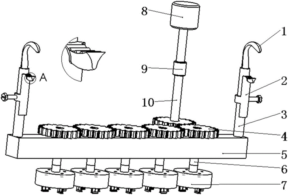
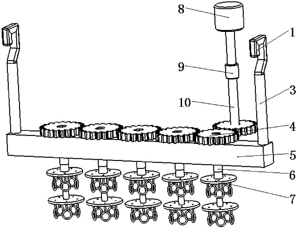
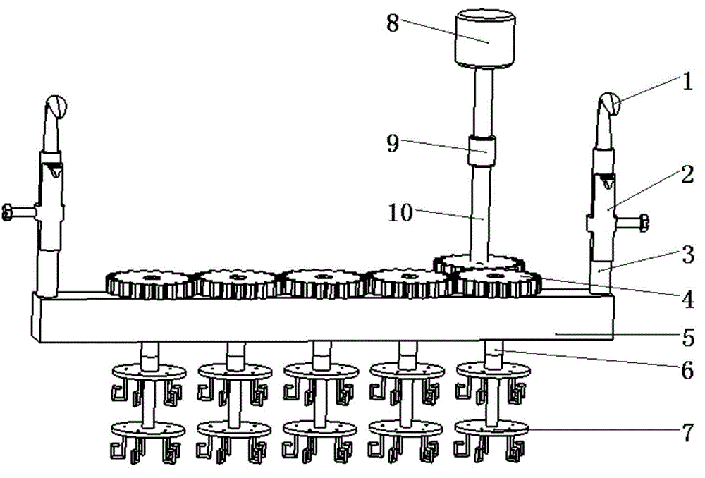
[0032] Such as Figure 1-3As shown, a kind of rotatable electroplating hanger that the present invention provides, comprises main bar 3, crossbeam 5, several gears 4, gear shaft 6 and the fixture 7 that is used for workpiece of different shapes and sizes; The two ends of described crossbeam 5 are vertical Fix the main rod 3, the upper end of the main rod 3 is provided with a hook 1, the shape of the hook 1 is arc-shaped or rectangular, when the hook 1 is arc-shaped, the main rod 3 is provided with a slidable clamping device 2 to ensure that the hook 1 Reliable contact with the pole bar, no de-electrification, and no swinging of the hanger during the electroplating process; a number of through holes are opened on the beam 5, and one of the gears 4 is assembled with the rotating shaft 10 and connected to the motor through the coupling 9...


PUM


Abstract

The invention discloses a rotatable electroplating rack. The rack comprises main rods, a cross beam, a plurality of gears, gear shafts and fixtures; the main rods are perpendicularly fixed at two ends of the cross beam; hooks are arranged at upper ends of the main rods; a plurality of through holes are formed in the cross beam; one of the gears and a rotating shaft are assembled and then are connected with an output end of a motor through a coupler; the rest gears and the gear shafts are assembled and then penetrate through the through holes; the fixtures used for electroplating of different types of workpieces are arranged at the other ends of the gear shafts; and meanwhile, special fixtures are designed for cylinder block type parts and thin and long shaft type parts particularly, so that the electroplating problems caused by the relatively large mass of the cylinder block type parts and the relatively small diameters of the thin and long shaft type parts are solved. The rack is simple in structure, multiple parts can be electroplated simultaneously, the workpieces are clamped firmly and reliably and are convenient to mount and dismount, the phenomenon of falling into a tank is avoided, the torque is input and the outer meshing gears rotate to drive the workpieces to rotate continuously in the electroplating process, the plating is uniform in thickness, the electric current density is increased, the electroplating time is shortened, and the efficiency is improved.

Description

technical field [0001] The invention relates to an electroplating rack, in particular to a rotatable electroplating rack. Background technique [0002] Electroplating is the process of plating a thin layer of metal or alloy on the surface of a metal substrate by the principle of electrolysis. During electroplating, the plated metal is used as the anode, and the workpiece to be plated is used as the cathode. The cations of the plated metal are reduced on the surface of the workpiece to be plated to form a coating. The solution containing the plating metal cations is used as the electroplating solution to keep the concentration of the plating metal cations constant. The purpose of electroplating is to use the coating on the surface of the substrate to enhance the corrosion resistance, wear resistance, hardness, conductivity, lubricity, heat resistance and other special properties of the metal. It can also be used to repair wear and process False artifacts. [0003] The hange...

Claims


Application Information

Patent Timeline
Patent Type & Authority Applications(China)
IPC IPC(8): C25D17/06
CPCC25D17/06
Inventor 李湘生马再权陈力杨宇孙红伟张帅
Owner ZHEJIANG SCI-TECH UNIV
Learn More