
Independent partitioned grate firing flue gas circulation combustion system and use method thereof

A flue gas circulation and combustion system technology, applied in the direction of combustion methods, solid fuel combustion, combustion equipment, etc., can solve the problems of large amount of NOx, achieve the effect of promoting combustion, promoting burnout, and stable conditions

Active Publication Date: 2017-04-26
HARBIN INST OF TECH
View PDF10 Cites 13 Cited by
  • Summary
  • Abstract
  • Description
  • Claims
  • Application Information

AI Technical Summary

Problems solved by technology

[0005] The present invention aims to solve the technical problem that the amount of NOx generated in the combustion process of the existing layer-fired boiler is large, thereby providing an independent zoned layer-fired flue gas circulation combustion system and its use method

Method used


Image

  • Independent partitioned grate firing flue gas circulation combustion system and use method thereof
  • Independent partitioned grate firing flue gas circulation combustion system and use method thereof

Examples


specific Embodiment approach 1

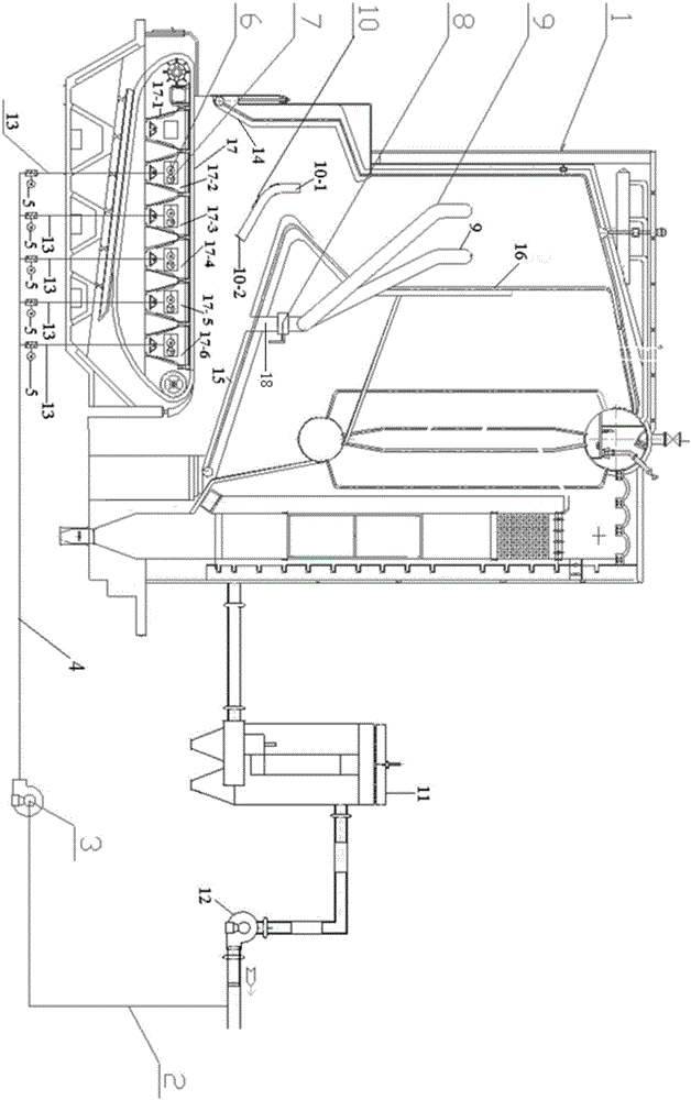
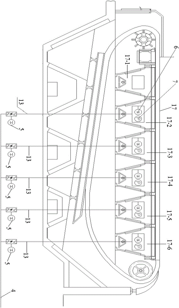
[0025] Specific implementation mode one: as Figure 1-2 , the present embodiment is an independent zoned layer combustion flue gas circulation combustion system which is composed of a layer combustion boiler 1, a dust collector 11, a layer combustion boiler induced draft fan 12, a recirculation induced draft fan input pipeline 2, a recirculation induced draft fan 3, and a recirculation induced draft fan 3. Circulation induced draft fan output pipeline 4, recirculation branch pipeline 13, branch pipeline electric control valve 5, air chamber electric control valve 6, air chamber pressure measurement gauge 7, flue gas communication pipeline from rear arch to boiler rear wall 9 , the connecting pipeline regulating valve 8 and the partition arch 10 are composed;

[0026] The inlet of the dust collector 11 is connected with the flue outlet of the boiler, the outlet of the dust collector 11 is connected with the inlet of the induced draft fan 12 of the layer-fired boiler, and one en...

specific Embodiment approach 2

[0034] Embodiment 2: The difference between this embodiment and Embodiment 1 is that the flue gas communication pipeline 9 from the rear arch to the boiler rear wall is made of high temperature resistant stainless steel 310S. Others are the same as the first embodiment.

specific Embodiment approach 3

[0035] Specific implementation mode three: This implementation mode is a method of using an independent partition layer combustion flue gas circulation combustion system in specific implementation mode one, specifically:

[0036] 1. Turn on the recirculation induced draft fan 3, and the hot flue gas in the stable section of the outlet of the layer-fired boiler induced draft fan 12 is sucked by the recirculation induced draft fan 3, which in turn passes through the recirculation induced draft fan input pipeline 2, and the recirculation induced draft fan output pipeline 4 , The recirculation branch pipeline 13 enters the second to sixth air chambers below the fire grate 17 of the floor-fired boiler, and the recirculation flue gas volume is controlled by the recirculation induced draft fan 2 to account for 15% to 25% of the actual total flue gas load of the boiler ; Among them, when the load of the boiler is greater than or equal to 85% of the rated load, the total amount of recir...


PUM


Abstract

The invention provides an independent partitioned gate firing flue gas circulation combustion system and a use method of the independent partitioned gate firing flue gas circulation combustion system and relates to a low-nitrogen combustion system and a use method of the low-nitrogen combustion system. The independent partitioned gate firing flue gas circulation combustion system aims at solving the technical problem of generating a large amount of NOx in the combustion process of an existing gate firing boiler. The system is composed of a recirculation induced draft fan, branch pipeline electric regulating valves, a flue gas communication pipeline from a rear arch to the back wall of a boiler, a communication pipeline regulating valve and a partitioned arch. An inlet of the recirculation induced draft fan communicates with an outlet of a gate firing boiler induced draft fan. An outlet of the recirculation induced draft fan communicates with fire grate air chambers. Each recirculation branch pipeline is provided with the electric regulating valve. The flue gas communication pipeline which is on the rear arch of a hearth and is guided out of the rear arch of the hearth to the back wall of the boiler is provided with the regulating valve. The partitioned arch is arranged below the rear arch of the hearth. The use method of the system includes the steps that firstly, the total amount of recirculation flue gas is controlled; secondly, the recirculation flue gas amount in all the air chambers is controlled; and thirdly, the communication pipeline regulating valve is controlled. The independent partitioned gate firing flue gas circulation combustion system and the use method have the following beneficial effect that the nitrogen reduction efficiency ranges from 25% to 27%.

Description

technical field [0001] The invention relates to a low-nitrogen combustion system and its application method. Background technique [0002] There are about 546,000 coal-fired industrial boilers in service in my country, accounting for 85% of the total number of industrial boilers currently in service, and increasing at a rate of about 1.5% every year. The annual coal consumption of coal-fired industrial boilers is 500-600 million tons, accounting for about 18% of the country's total annual coal consumption. The annual total energy consumption and pollution discharge of industrial boilers both rank second in the national industrial industry. [0003] In the research on the emission reduction of industrial boiler pollutants, SO 2 The research on smoke and dust was carried out relatively early, and a lot of research results have been obtained, and they have been applied industrially. Due to the characteristics of low-temperature combustion of industrial boilers, the amount of...

Claims


Application Information

Patent Timeline
Patent Type & Authority Applications(China)
IPC IPC(8): F23B80/02F23L1/02F23L9/06
CPCF23B80/02F23L1/02F23L9/06
Inventor 高建民栾积毅吴少华赵广播杜谦赵义军秦裕琨
Owner HARBIN INST OF TECH
Learn More