Nozzle, nozzle wall and compressed air energy storage afterburning chamber

A technology of nozzles and central nozzles, which is applied in the field of nozzle walls, compressed air energy storage supplementary combustion chambers, and nozzles, and can solve problems such as high NOx emissions, small investment, and impact on system energy storage efficiency.

Pending Publication Date: 2022-08-05
XIAN THERMAL POWER RES INST CO LTD
View PDF0 Cites 0 Cited by
  • Summary
  • Abstract
  • Description
  • Claims
  • Application Information

AI Technical Summary

Problems solved by technology

At present, the earliest development is the post-combustion compressed air energy storage technology, which has the characteristics of large energy storage power and small investment, and the nozzle structure of the post-combustion chamber in the system is the core component of the system, which directly affects the post-combustion combustion temperature, NOx emissions and Burnout rate and other issues, but also affect system energy storage efficiency and other issues
However, the current spray gun structure has problems such as low combustion temperature, insufficient combustion and high NOx emissions.

Method used


Image

  • Nozzle, nozzle wall and compressed air energy storage afterburning chamber
  • Nozzle, nozzle wall and compressed air energy storage afterburning chamber
  • Nozzle, nozzle wall and compressed air energy storage afterburning chamber

Examples


Embodiment Construction

[0032] The present invention will be further described below in conjunction with the accompanying drawings and embodiments.

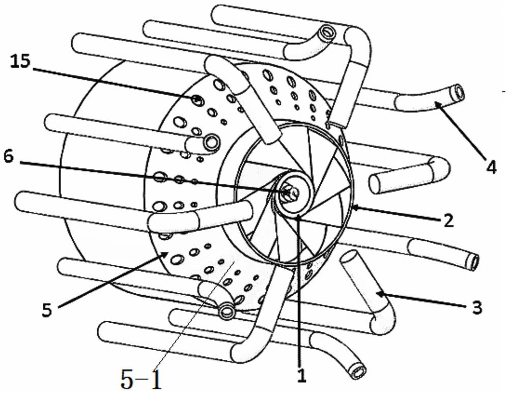
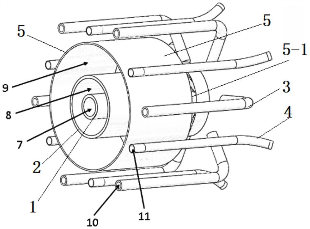
[0033] As shown in Fig. 1(a) and Fig. 1(b), the nozzle of the present invention includes a plurality of L-shaped back spray lances 3, a plurality of main fuel lances 4, and a central fuel cylinder 1 and a swirl air cylinder arranged coaxially from the center to the outside. 2 and the straight air cylinder 5; the outlet end of the central fuel cylinder 1 is provided with a spiral atomizing nozzle 6, and the specific form of the spiral atomizing nozzle 6 can be: a spiral structure 6-1 is arranged in the inner cavity of the outlet end of the central fuel cylinder 1, The helical structure 6-1 and the outlet end of the central fuel cylinder 1 together form the helical atomizing nozzle 6. For details, refer to Figure 5 , the overall structure of the helical structure 6-1 is a tapered structure with the same pitch and a gradual radius. With reference to Fig. ...


PUM


Abstract

The invention discloses a nozzle, a nozzle wall and a compressed air energy storage afterburning chamber. The nozzle comprises a plurality of back-spraying spray guns, a plurality of main fuel spray guns, a center fuel barrel, a rotational flow air barrel and a direct flow air barrel, a spiral atomizing nozzle is arranged at the outlet end of the central fuel barrel; rotational flow blades are arranged at the outlet end of the rotational flow air duct in an annular gap between the central fuel barrel and the rotational flow air duct; the outlet end of the direct-flow air duct is provided with a gradually-shrunk section, the small end of the gradually-shrunk section is connected with the outer wall of the outlet end of the rotational-flow air duct, a plurality of circles of round holes are formed in the gradually-shrunk section, and the diameter of the outer-side round holes is larger than that of the inner-side round holes; the plurality of back-spraying spray guns and the plurality of main fuel spray guns are alternately and uniformly arranged on the periphery of the direct-flow air duct; an outlet of the back-spraying spray gun is located on the downstream of the direct-flow air duct gradually-shrinking section and faces the gradually-shrinking section. An outlet of the main fuel spray gun inclines from inside to outside in the radial direction of the direct-flow air duct. The nozzle is simple in structure and small in investment, and the characteristics of combustion chamber temperature, combustion efficiency and pollutant control are well considered.

Description

technical field [0001] The invention belongs to the technical field of clean fuel combustion, and relates to a nozzle, a nozzle wall and a compressed air energy storage supplementary combustion chamber. Background technique [0002] At present, under the dual-carbon goal, in order to solve the contradiction between supply and demand of new energy power generation, continue to develop large-scale, long-term, low-cost, and high-efficiency energy storage technology. Compressed air energy storage technology is one of the energy storage technologies that meet this requirement. At present, the supplementary combustion compressed air energy storage technology is the earliest developed technology, which has the characteristics of high energy storage power and small investment. The structure of the supplementary combustion chamber nozzle in the system is the core component of the system, which directly affects the supplementary combustion combustion temperature, NOx emissions and Bur...

Claims


Application Information

Patent Timeline
Patent Type & Authority Applications(China)
IPC IPC(8): F23D14/08F23D14/58F23D14/70F23D14/46F28D20/00
CPCF23D14/08F23D14/58F23D14/70F23D14/46F28D20/00F23D2203/007F23D2900/14003F23D2900/14241F28D2020/006Y02E60/16
Inventor 姬海民韩伟黄晓明宋晓辉陆续姚明宇付康丽
Owner XIAN THERMAL POWER RES INST CO LTD
Why Eureka
Try Eureka