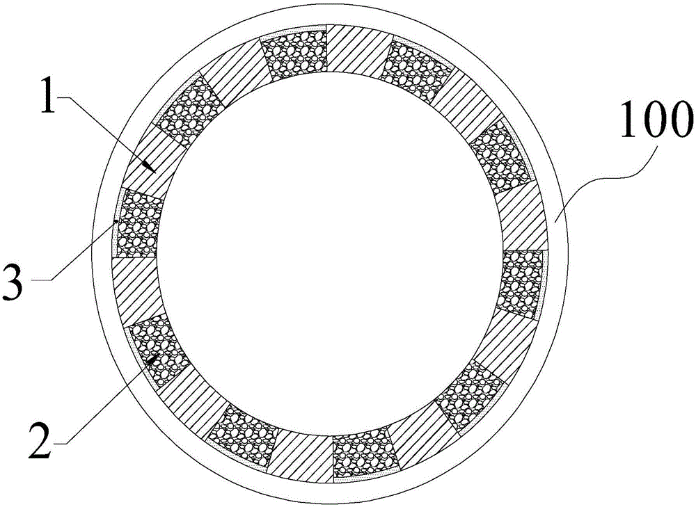
Rotary kiln liner structure and laying method
A rotary kiln and kiln lining technology, applied in the field of rotary kiln, can solve the problems of service life impact, low heat utilization rate of rotary kiln, high thermal conductivity of refractory bricks, etc., to reduce heat radiation loss, improve heat utilization efficiency, and service life Improved effect
- Summary
- Abstract
- Description
- Claims
- Application Information
AI Technical Summary
Problems solved by technology
Method used
Image

Examples
Embodiment 1
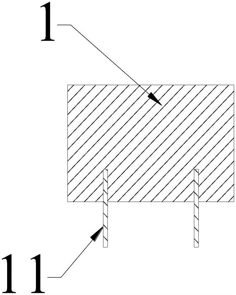
[0029] The preform 1 and the castable 2 are prepared by conventional methods from the following raw materials in parts by weight:
[0030] 25 parts of high-alumina slag with a particle size of 0-2 mm, 20 parts of high-alumina slag with a particle size of 2-5 mm, 22 parts of high-alumina slag with a particle size of 5-10 mm, 20 parts of bauxite powder with a particle size of 200 mesh, and micronized silicon powder 3 parts of dust powder, 3 parts of high alumina cement with a particle size of 200 mesh, 5 parts of alumina micropowder with a particle size of 200 mesh, and 2 parts of sodium hexametaphosphate with a particle size of 1-3mm.
[0031] The raw material of this component can make the prefabricated part 1 and the casting material 2 have better performances of high temperature resistance and wear resistance.
Embodiment 2
[0033] The preform 1 and the castable 2 are prepared by conventional methods from the following raw materials in parts by weight:
[0034] 28 parts of high-alumina slag with a particle size of 0-2 mm, 18 parts of high-alumina slag with a particle size of 2-5 mm, 18 parts of high-alumina slag with a particle size of 5-10 mm, 22 parts of bauxite powder with a particle size of 200 mesh, and micronized silicon powder 2 parts of dust powder, 4 parts of high alumina cement with a particle size of 200 mesh, 6 parts of alumina micropowder with a particle size of 200 mesh, and 2 parts of sodium hexametaphosphate with a particle size of 1-3mm.
[0035] The raw material of this component can make the prefabricated part 1 and the casting material 2 have better performances of high temperature resistance and wear resistance.
PUM
| Property | Measurement | Unit |
|---|---|---|
| compressive strength | aaaaa | aaaaa |
| service temperature | aaaaa | aaaaa |
| particle size | aaaaa | aaaaa |
Abstract
Description
Claims
Application Information
 - R&D
- Intellectual Property
- Life Sciences
- Materials
- Tech Scout
- Unparalleled Data Quality
- Higher Quality Content
- 60% Fewer Hallucinations
Browse by: Latest US Patents, China's latest patents, Technical Efficacy Thesaurus, Application Domain, Technology Topic, Popular Technical Reports.
© 2025 PatSnap. All rights reserved.Legal|Privacy policy|Modern Slavery Act Transparency Statement|Sitemap|About US| Contact US: help@patsnap.com