Hydrogen sensor

A sensor and sensor housing technology, applied in the field of sensors, can solve the problems of inability to function, the electrode is separated from mass transfer, the electrolyte is dry, etc., to avoid poor contact, increase the contact area, and improve the response speed.

Inactive Publication Date: 2017-04-26
ASENSOR TECH
View PDF10 Cites 4 Cited by
  • Summary
  • Abstract
  • Description
  • Claims
  • Application Information

AI Technical Summary

Problems solved by technology

When there is strong shock and vibration in the environment where the sensor is used, the liquid electrolyte will fly out in the form of foam, which will cause the electrode to separate from the electrolyte and cause poor mass transfer; secondly, the electrolyte particles flying out in foam will pass through the O-type The overflow of the edge of the ring will cause the sensor to leak; in addition, even in normal use, the change of the ambient humidity will affect the concentration of the electrolyte, causing the electrolyte to dry up or leak; 2) the above liquid electrolyte and the working electrode , There is a layered contact between the counter electrode and the reference electrode. Due to the long mass transfer distance between the working electrode and the counter electrode, the hydrogen ions produced on the working electrode and the oxygen ions produced on the counter electrode have to go through a long path. In order to combine into water molecules, the electrons generated by the reaction have to go through a long distance to complete the transmission with the external circuit, which directly leads to the long response time of the sensor; 3) the catalyst in the traditional electrochemical sensor is The tiled form is fixed on the catalyst substrate by its own adhesive force. In fact, only the outermost layer of the catalyst distributed in this form can participate in the chemical reaction. The catalyst in the inner layer is covered by the catalyst on the surface layer. The protons generated by the reaction need to pass through the inner catalyst wall to reach the electrolyte part, which prolongs the response time of the sensor to a certain extent.

Method used


Image

  • Hydrogen sensor
  • Hydrogen sensor
  • Hydrogen sensor

Examples


Embodiment Construction

[0025] In order to have a clearer understanding of the technical features, purposes and effects of the present invention, the specific implementation manners of the present invention will now be described in detail with reference to the accompanying drawings.

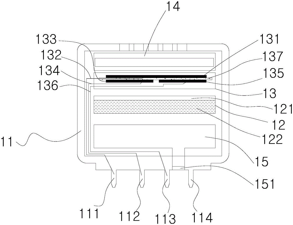
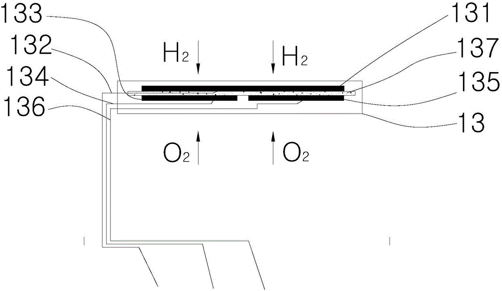
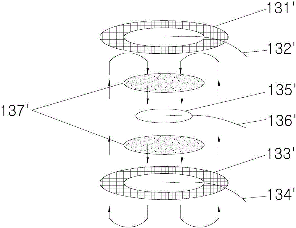
[0026] Such as figure 1 As shown, in the hydrogen sensor of the present invention, it includes a sensor housing 11, a gas reaction center 13 arranged in the sensor housing 11, and the gas reaction center 13 includes a working electrode 131, a counter electrode 133, a reference electrode 135 and an electrolyte 137 , the electrolyte 137 is a solid electrolyte, and the working electrode 131 , the counter electrode 133 , and the reference electrode 135 are all fixed on the electrolyte 137 .

[0027] The sensor housing 11 serves as a protective support for the entire sensor, and is connected to the external PCB board and the internal gas reaction center 13 through the pins 111, 112, 113 at the bottom of the sensor, and trans...


PUM


Abstract

The invention relates to a hydrogen sensor comprising a sensor shell and a gas reaction center in the sensor shell. The gas reaction center comprises a work electrode, a counter electrode, a reference electrode and solid electrolyte. The work electrode, the counter electrode and the reference electrode are fixed to the electrolyte. The solid electrolyte is used in the hydrogen sensor, because the electrolyte is solid and the work electrode, the counter electrode and the reference electrodes are fixed to the electrolyte and can make full contact with the electrolyte, the contact area of the electrodes and the electrolyte is increased, the whole electrodes can conduct proton transfer, the poor contact phenomenon between the electrolyte and the electrodes and the sensor liquid leakage or electrolyte dryout phenomenon can be avoided, and response speed of the hydrogen sensor is greatly increased.

Description

technical field [0001] The invention relates to the field of sensors, more specifically, to a hydrogen sensor. Background technique [0002] The current new energy vehicles mainly include fuel cell vehicles and electric vehicles. Fuel cell vehicles are new energy vehicles developed with pure hydrogen as energy and combined with the power performance of fuel cells. And the tightness of the pipeline has put forward requirements. Once a leak occurs, the consequences will be disastrous; current electric vehicles generally use lithium-ion batteries as the power source, and when the lithium battery is overcharged or short-circuited, the internal substances of the battery will decompose and produce hydrogen. At the same time, it is used as a battery temperature management The coolant of the main means will also decompose and produce hydrogen when the charging voltage reaches a certain level. [0003] Hydrogen is a colorless, odorless, non-toxic, flammable and explosive gas. When t...

Claims


Application Information

Patent Timeline
Patent Type & Authority Applications(China)
IPC IPC(8): G01N27/407
CPCG01N27/407
Inventor 廖晓霞赵旭
Owner ASENSOR TECH
Why Eureka
Try Eureka