
Indoor personnel positioning monitoring system and method

A personnel positioning and monitoring system technology, applied in the field of indoor personnel positioning monitoring system, can solve the problems of insufficient positioning accuracy, limited precise positioning, short line-of-sight and transmission distance, etc., to achieve the effect of easy maintenance and easy capacity expansion

Inactive Publication Date: 2017-04-26
SHANGHAI GONGJIN COMM TECH
View PDF4 Cites 3 Cited by
  • Summary
  • Abstract
  • Description
  • Claims
  • Application Information

AI Technical Summary

Problems solved by technology

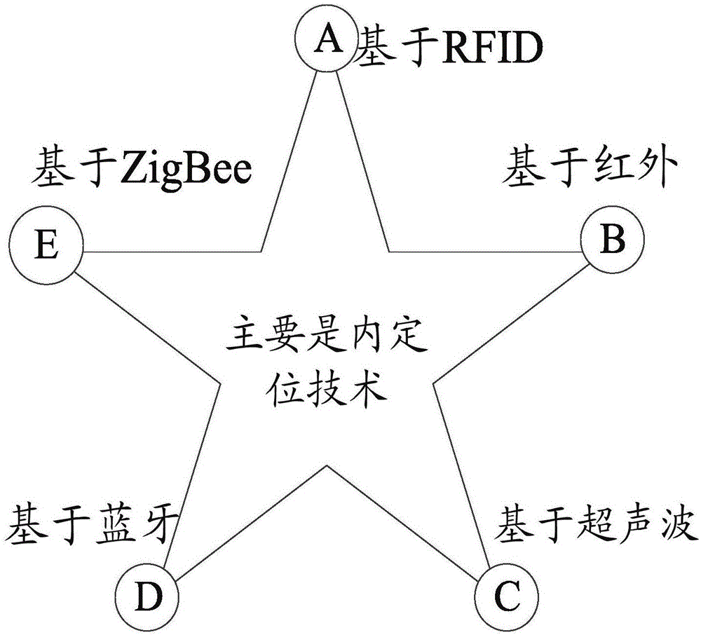
[0003] Existing traditional indoor positioning systems, such as figure 1 As shown, infrared technology: Discrete infrared technology is used to realize indoor positioning. The two major shortcomings of short line-of-sight and short transmission distance make the indoor positioning effect very poor, and it is only suitable for short-distance transmission, and it is easy to be detected by fluorescent lamps or The light interference in the room has limitations in precise positioning; ultrasonic technology: mainly adopts the reflective ranging method, and determines the position of the object through algorithms such as triangulation, that is, emits ultrasonic waves and receives echoes generated by the measured object, according to The distance to be measured is calculated by the time difference between the echo and the transmitted wave. Ultrasonic positioning has poor anti-interference ability and a small positioning range; the positioning accuracy of network-based devices such as ultra-wideband or Bluetooth is insufficient. Although traditional satellite positioning systems such as GPRS can position with high precision outdoors only

Method used


Image

  • Indoor personnel positioning monitoring system and method
  • Indoor personnel positioning monitoring system and method
  • Indoor personnel positioning monitoring system and method

Examples


Embodiment Construction

[0081] In order to describe the technical content of the present invention more clearly, further description will be given below in conjunction with specific embodiments.

[0082] The indoor personnel positioning monitoring system includes:

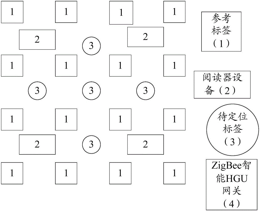
[0083] Reference tags, used to determine the location of RFID active tags;

[0084] The RFID active tag is used to determine the position of the indoor personnel according to the relative positional relationship between the RFID active tag and the reference tag;

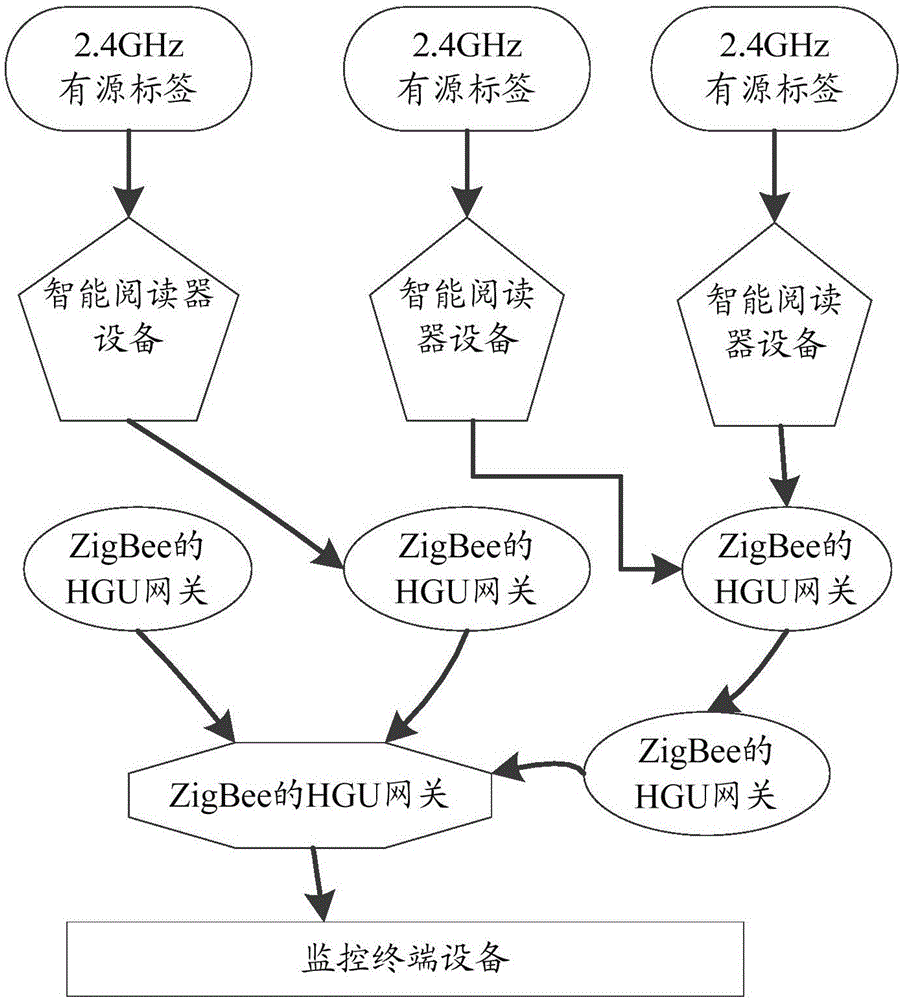
[0085] RFID reader, for collecting the position information of described RFID active tag, and send this position information to ZigBee-HGU gateway;

[0086] The ZigBee-HGU gateway is used to accept the information of the RFID reader and send the information to the PC.

[0087] Preferably, the RFID active tag includes a first radio frequency module, a first signal processing module and a first control module, and the first radio frequency module is connected to the first signal...


PUM


Abstract

The invention relates to an indoor personnel positioning monitoring system and method. The system comprises a reference tag used for determining the position of an RFID active tag, the RFID active tag for determining the position of indoor personnel according to the relative position relation between the RFID active tag and the reference tag, an RFID reader used for collecting the position information of the RFID active tag and sending the position information to a ZigBee-HGU gateway, and the ZigBee-HGU gateway used for receiving the information of the RFID reader and sending the information to a PC terminal. By using the system and the method, the cost is low, the power consumption is low, the networking is simple, the layout is convenient, the system is very suitable for the positioning of indoor personnel, the development prospect is same with that of the computer and the Internet, the system integrates into every corner of the daily life of people, convenience and rapidity are brought to the life of the people, so the system has great research significance and market value and has a wide range of application.

Description

technical field [0001] The present invention relates to the technical field of communication, in particular to the technical field of wireless communication, in particular to an indoor personnel positioning monitoring system and method. Background technique [0002] At present, the indoor positioning technology is mainly based on: infrared positioning, ultrasonic positioning, Bluetooth technology positioning, network positioning, RFID radio frequency identification positioning and ZigBee technology positioning and so on. In the wave of globalization of information construction, the Internet of Things technology is outstanding, and the two key technologies of the Internet of Things, radio frequency identification and ZigBee, are used in more and more fields. ZigBee technology is a new two-way wireless communication technology, which is convenient for network maintenance and capacity expansion, and also has the advantages of easy deployment and strong network self-healing abil...

Claims


Application Information

Patent Timeline
IPC IPC(8): G01S5/06G01S11/06H04W4/02H04W48/10H04W48/16H04W64/00
CPCG01S5/06G01S11/06H04W4/023H04W48/10H04W48/16H04W64/003Y02D30/70
Inventor 陈学凯
Owner SHANGHAI GONGJIN COMM TECH
Learn More