Liquid crystal display module laminated structure and electronic equipment

A liquid crystal display module and liquid crystal display module technology, applied in the electronic field, can solve the problem that the NFC antenna cannot be detected outside the metal back shell, etc., and achieve the effects of wide application range, sensitive and reliable use, and improved integration

Pending Publication Date: 2017-04-26
上海蓝沛信泰光电科技有限公司
View PDF13 Cites 9 Cited by
  • Summary
  • Abstract
  • Description
  • Claims
  • Application Information

AI Technical Summary

Problems solved by technology

[0005] In view of the above-mentioned shortcomings of the prior art, the purpose of the present invention is to provide a liquid crystal display module laminated structure and electronic equipment to solve the problem in the prior art that the NFC antenna cannot be detected outside the metal back shell

Method used


Image

  • Liquid crystal display module laminated structure and electronic equipment
  • Liquid crystal display module laminated structure and electronic equipment
  • Liquid crystal display module laminated structure and electronic equipment

Examples


Embodiment 1

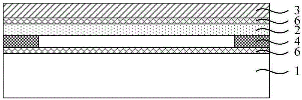
[0040] see figure 1 , the present invention provides a liquid crystal display module laminated structure, said laminated structure comprises:

[0041] Liquid crystal display module layer 1;

[0042] The NFC antenna coil layer 2 arranged on the liquid crystal display module layer 1;

[0043] A cover plate 3 disposed on the NFC antenna coil layer 2;

[0044] And the magnetically permeable material layer 4 arranged under the NFC antenna coil layer 2 ; and the magnetically permeable material layer 4 is located above the liquid crystal display module layer 1 .

[0045] Specifically, the liquid crystal display module layer 1 is used as a basic module of the liquid crystal display module for displaying images. As the basic structure of the liquid crystal display module, the liquid crystal display module layer 1 sequentially includes a backplane, a backlight source, a lower polarizer, a color filter and an upper polarizer from bottom to top. As an example, a front frame may also ...

Embodiment 2

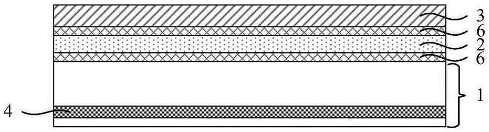
[0055] This embodiment adopts basically the same technical solution as Embodiment 1. The difference is that in Embodiment 1, the magnetically permeable material layer 4 is located above the liquid crystal display module layer 1, while in this embodiment, the magnetically conductive material layer 4 is located above the liquid crystal display module layer 1. The magnetic material layer 4 is located in the liquid crystal display module layer 1 .

[0056] Specifically, the liquid crystal display module layer 1 is used as a basic module of the liquid crystal display module for displaying images. As the basic structure of the liquid crystal display module, the liquid crystal display module layer 1 sequentially includes a backplane, a backlight source, a lower polarizer, a color filter and an upper polarizer from bottom to top. As an example, a front frame may also be included above the upper polarizer; a main control board and a backlight module lighting device may be included unde...
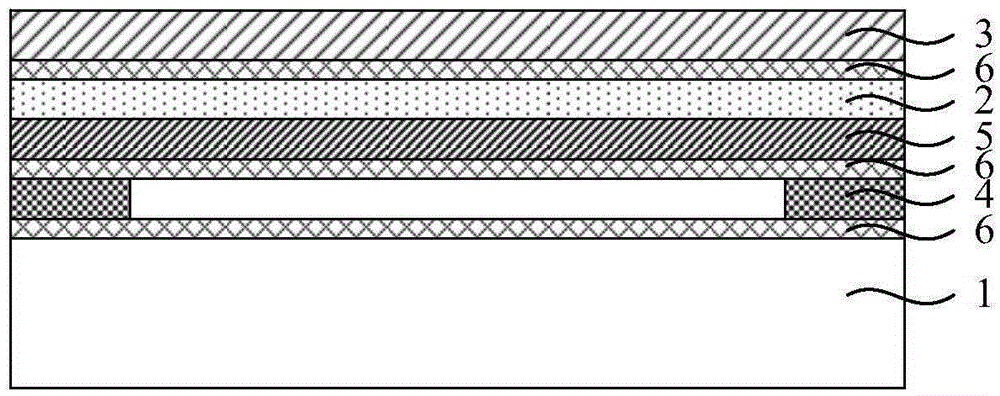
Embodiment 3

[0065] This embodiment adopts basically the same technical solution as Embodiment 1 or Embodiment 2, except that in this embodiment, the laminated structure further includes a touch sensor embedded in the liquid crystal display module layer 1 .

[0066] The LCD module layer with embedded touch sensors is already used in some high-end LCD screens, and there will be no additional touch layer in this LCD screen. Compared with Embodiment 1 and Embodiment 2, this embodiment can realize a touch function because the laminated structure further includes a touch sensor embedded in the liquid crystal display module layer 1 .


PUM


Abstract

The invention provides a liquid crystal display module laminated structure and electronic equipment. The laminated structure comprises a liquid crystal display module layer, an NFC antenna coil layer arranged on the liquid crystal display module layer, a cover plate arranged on the NFC antenna coil layer and a magnetic-conductive material layer arranged below the NFC antenna coil layer and located above or below the liquid crystal display module. The laminated structure has the advantages that the new laminated structure combines the NFC module and the display module, an NFC function is added to the touch function of the liquid crystal display module, and the integration level of the liquid crystal display module is further increased; due to the fact that the NFC module is located above a screen, sensitivity and reliability during use are achieved, a wide application range is achieved, and the NFC module is especially suitable for fields, that equipment rear cannot be touched, such as vehicular screens and automatic telling machine screens; from the perspective of cost, an NFC antenna can hopefully share the base material with the touch screen, and cost can be lowered greatly.

Description

technical field [0001] The invention belongs to the field of electronics, and relates to a laminated structure of a liquid crystal display module and electronic equipment. Background technique [0002] With the development of the near-field communication function of mobile devices at the present stage, the NFC (Near Field Communication, short-range wireless communication technology, NFC for short) function will be configured in more handheld devices. NFC near-field communication technology is evolved from the integration of non-contact radio frequency identification (RFID) and interconnection technologies. It combines inductive card readers, inductive cards and point-to-point functions on a single chip, and can be compatible with Devices are identified and data exchanged. For example, a mobile phone with NFC function can be used as airport boarding verification, building access control key, traffic card, credit card, payment card, etc., which brings great convenience to peo...

Claims


Application Information

Patent Timeline
Patent Type & Authority Applications(China)
IPC IPC(8): G02F1/1333G06F3/041
CPCG02F1/1333G02F1/13338G06F3/0412
Inventor 杨兆国徐厚嘉林晓辉刘升升
Owner 上海蓝沛信泰光电科技有限公司
Why Eureka
Try Eureka