Abrasive particle flow field analysismethod based on CFD-DEM coupling model

A technology of coupling model and abrasive flow, which is applied in special data processing applications, complex mathematical operations, instruments, etc., and can solve problems such as difficult to precisely control processing parameters.

Active Publication Date: 2017-04-26
ZHEJIANG UNIV OF TECH
View PDF4 Cites 22 Cited by
  • Summary
  • Abstract
  • Description
  • Claims
  • Application Information

AI Technical Summary

Problems solved by technology

[0004] The purpose of the present invention is to overcome the problem that it is difficult to accurately analyze the abrasive flow movement in the existing abrasive flow processing, and then it is difficult to accurately control the processing parameters, and provides a method that introduces the discrete element model into the CFD model and solves the problem through numerical calculation. The abrasive flow field analysis method based on the coupled model can effectively analyze the movement of abrasive particle flow in the entire flow field, and then realize the precise control of abrasive flow processing.

Method used


Image

  • Abrasive particle flow field analysismethod based on CFD-DEM coupling model
  • Abrasive particle flow field analysismethod based on CFD-DEM coupling model
  • Abrasive particle flow field analysismethod based on CFD-DEM coupling model

Examples


Embodiment Construction

[0084] The present invention will be described in detail below in conjunction with a specific example.

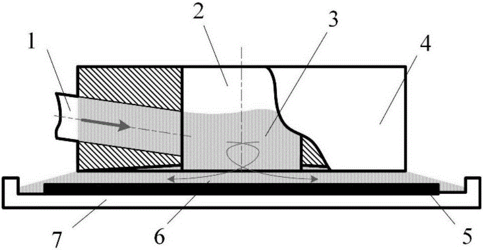
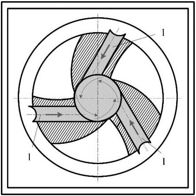
[0085] Such as Figure 1-6 As shown, the specific embodiment adopts a three-inlet-surface restricted abrasive flow processing device to process the workpiece 2. The circular processing tool has three abrasive particle flow inlets 1 along the circumferential direction, and the abrasive particle flow 3 is driven by the water pump. From the abrasive particle flow inlet 1 into the unrestricted space 2 in the middle of the circular processing tool; after being fully mixed, the abrasive particle flow 3 enters the restricted space 6 at a higher flow rate, and then the abrasive particle flow 3 installed at the bottom of the circular processing tool The workpiece 2 is finished. Adopt the present invention to analyze the abrasive particle flow field at the workpiece surface in the processing method, the specific process is as follows:

[0086] (1) Establish the finite element model...


PUM


Abstract

The invention discloses an abrasive particle flow field analysis method based on a CFD-DEM coupling model. The method comprises the following steps of (1) building and solving an abrasive particle processing-oriented fluid phase control equation set, (2) solving an abrasive particle motion equation through a DEM theory according to a solution result achieved in the (1) step, (3) updating a position of the abrasive particles in a flow path according to the abrasive particle motion equation, and solving a new volume fraction and action force applied to the abrasive particles, (4) substituting a new fluid volume fraction and the action force applied to the abrasive particles to the (1) step for a new round calculation, continuously updating speed and position of each abrasive particle in a circulating way according to the above calculation process to evolving the whole abrasive particle flow processing system to achieve an abrasive particle flow motion rule. A method combining a computational fluid mechanics model and a discrete element theory model is introduced to the abrasive particle flow processing field; precise analysis can be conducted to abrasive particle movements; and abrasive particle processing technology parameters can be accurately adjusted and controlled.

Description

technical field [0001] The present invention relates to the technical field of precision finishing, and more specifically, relates to a method for analyzing abrasive particle flow field based on a CFD-DEM coupled model. Background technique [0002] Precision finishing technology is an important supporting technology for the development of modern industry. Among them, the fluid-based abrasive flow machining technology has incomparable advantages in some processing occasions due to the use of flexible fluids. Traditional abrasive flow processing can be generally divided into two categories, one is the traditional extrusion abrasive flow processing technology using strong viscosity fluid for extrusion processing, such as extrusion honing; the other is the use of weak viscosity or no Abrasive flow processing technology for viscous fluids, such as abrasive jet processing, elastic emission polishing, float polishing, chemical mechanical polishing and magnetorheological polishing...

Claims


Application Information

Patent Timeline
Patent Type & Authority Applications(China)
IPC IPC(8): G06F17/11G06F17/50
CPCG06F17/11G06F30/23
Inventor 计时鸣葛江勤谭大鹏袁智敏郑晨亮
Owner ZHEJIANG UNIV OF TECH
Why Eureka
Try Eureka