Current transformer with temperature measuring device

A technology of current transformer and temperature measuring device, applied in the direction of inductor, circuit, transformer, etc., can solve the problem that the installation of cable head test device is difficult to meet the design requirements, the installation of cable head test device of ring network cabinet is complicated, and the cable head test device is difficult to install. problems such as poor stability, to achieve the effect of reducing the probability of accidents, high reliability and high cost performance

Inactive Publication Date: 2017-04-26
BEIJING HEROSAIL POWER SCI & TECH
View PDF8 Cites 4 Cited by
  • Summary
  • Abstract
  • Description
  • Claims
  • Application Information

AI Technical Summary

Problems solved by technology

[0007] In the prior art, the temperature measuring device of the cable head of the ring network cabinet is a separate module, and the temperature measuring device of the cable head and the current transformer are two independent devices. After the current transformer is installed, the temperature measuring device of the cable head needs to be additionally installed; Due to the limited space in the ring network cabinet, the installation of the cable head test device of the ring network cabinet is complicated, and the installation of the cable head test device is difficult to meet the design requirements. The stability of the cable head test device is poor, causing the ring network cabinet to fail to operate normally.

Method used


Image

  • Current transformer with temperature measuring device
  • Current transformer with temperature measuring device

Examples


Embodiment Construction

[0030] The present invention is described in detail below with reference to accompanying drawing and embodiment:

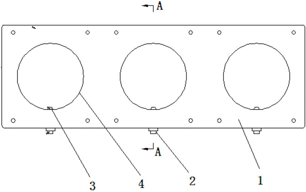
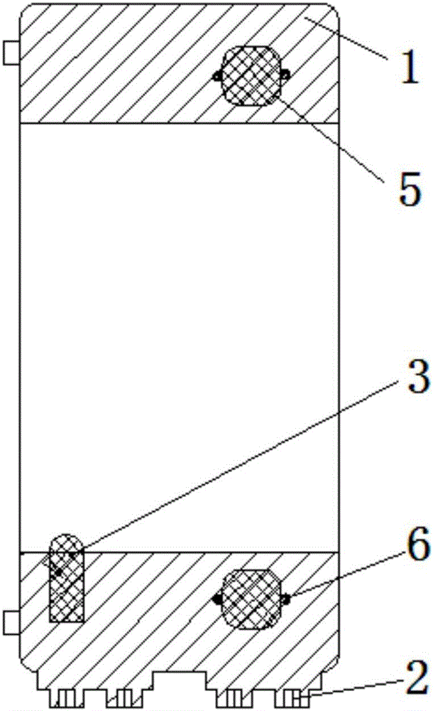
[0031] attached Figure 1-2 It can be seen that a current transformer with a temperature measuring device includes a housing 1, an iron core, a copper coil and a terminal 2, an iron core 5 is arranged in the housing, and a copper coil 6 is wound on the iron core 5, The casing 1 and the iron core 5 are integrally formed. The iron core 5 is provided with a through hole 4 penetrating through the iron core and the casing. The surface of the through hole 4 is provided with a temperature sensor 3 .

[0032] The iron core 5 is composed of circular closed multi-layer silicon steel sheets.

[0033] The temperature sensor 3 is a thermal resistance sensor.

[0034] The shell is made of epoxy resin poured by APG automatic pressure gel technology.

[0035] The cross-sectional diameter of the copper coil is 2mm, used as a secondary coil, and the number of turns is determined...


PUM

PropertyMeasurementUnit
diameteraaaaaaaaaa
electrical resistanceaaaaaaaaaa

Abstract

The invention relates to a current transformer with a temperature measuring device. The current transformer comprises a shell, an iron core, a copper coil and a terminal; the iron core is arranged in the shell; the copper coil is wound on the iron core; the shell and the iron core are of an integrated structure; the inside of the iron core is provided with a through hole which penetrates through the iron core and the shell; and the surface of the through hole is provided with a temperature sensor. According to the current transformer with the temperature measuring device provided by the invention, a thermal resistance temperature sensor is directly poured in the shell of the current transformer, the current transformer and the temperature measuring device are combined, and the integration degree is greatly improved. The current transformer can not only output secondary currents, but can also output temperature signals, thereby enriching the functions of the current transformer; the temperature sensor is directly poured in the shell of the current transformer, so that mounting parts of the temperature sensor are saved; and while a temperature sensor probe directly faces a cable head, which has a higher reliability structurally and functionally.

Description

technical field [0001] The invention relates to a current transformer, in particular to a current transformer with a temperature measuring device. Background technique [0002] The current transformer is a sensor that enables secondary equipment such as measuring instruments and relay protection in the power system to obtain primary circuit current information, and enables important electrical equipment in the power system to undertake the isolation between high and low voltage systems and the high voltage to low voltage. Transformation functions. Whether the current transformer itself works normally or not is of great significance to the safety of the power system and the normal operation of protection, measurement and other equipment. [0003] The principle of current transformer is based on the principle of electromagnetic induction. A current transformer consists of a closed core and windings. Its primary winding has very few turns, and it is connected in series in th...

Claims


Application Information

Patent Timeline
Patent Type & Authority Applications(China)
IPC IPC(8): H01F38/30H01F27/40
CPCH01F38/30H01F27/402H01F2027/406
Inventor 张炜董帅
Owner BEIJING HEROSAIL POWER SCI & TECH
Why Eureka
Try Eureka