Automatic arranging and clamping equipment for battery pole groups and cast welding auxiliary device of using automatic arranging and clamping equipment
A battery pole group and driving device technology, applied in battery assembly, secondary battery manufacturing, sustainable manufacturing/processing, etc., can solve the problem that the pole group is not tightly clamped, the clamp pressing rod is not pressed in place, and the response is slow. and other problems, to achieve the effect of high work efficiency, short pressing stroke and fast response
- Summary
- Abstract
- Description
- Claims
- Application Information
AI Technical Summary
Problems solved by technology
Method used
Image
Examples
Embodiment 1
[0045] Embodiments of the present invention are described in detail below, examples of which are shown in the drawings, wherein the same or similar reference numerals designate the same or similar elements or elements having the same or similar functions throughout. The embodiments described below by referring to the figures are exemplary and are intended to explain the present invention and should not be construed as limiting the present invention.
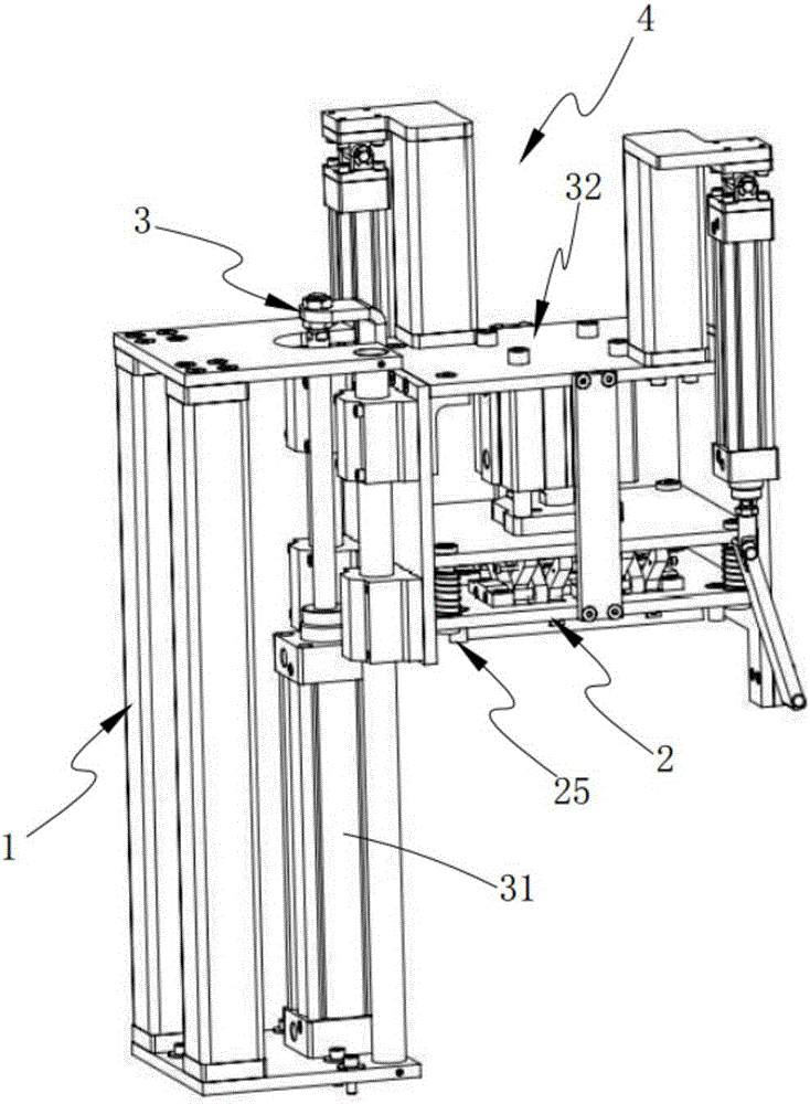
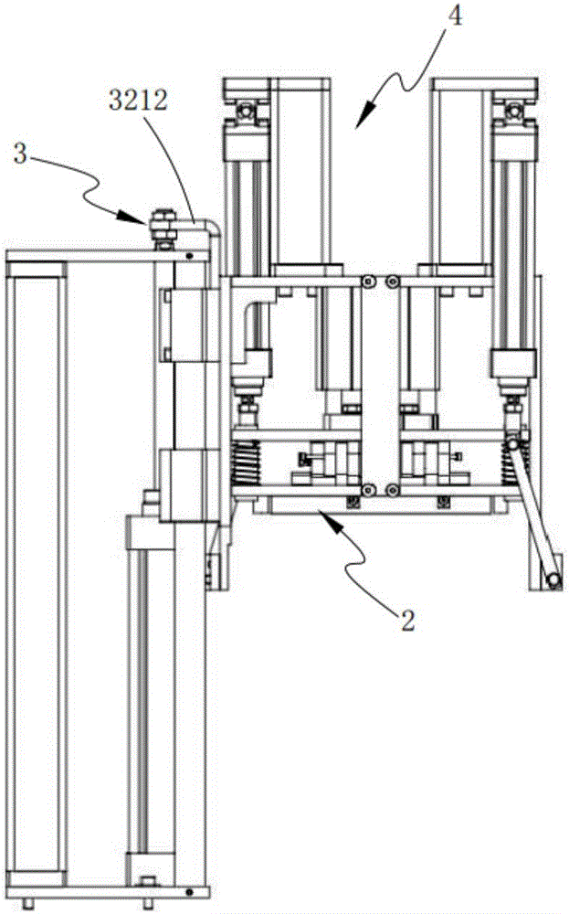
[0046] Refer to the attached figure 1 and figure 2 A battery electrode group automatic assembly equipment according to Embodiment 1 of the present invention is described.
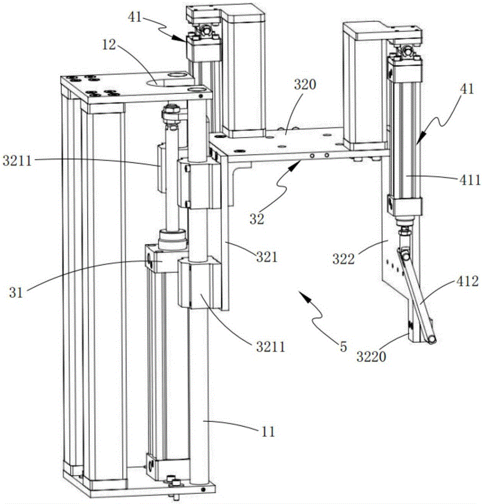
[0047] Such as figure 1 and figure 2 As shown, a battery pole group automatic assembly equipment includes a support base 1 and a shaping mechanism 2 for automatically arranging the pole group lugs of the jig 20, and also includes a lifting assembly 3 and a clamping mechanism 4. The assembly 3 includes a first driving device 31 and a mold base 32 suspende...
Embodiment 2
[0055] Figure 5 It is a schematic structural diagram of Embodiment 2 of an automatic assembly equipment for battery pole groups in the present invention; Figure 5 As shown, the components that are the same as or corresponding to those in the first embodiment are marked with the corresponding reference numerals in the first embodiment. For the sake of simplicity, only the differences from the first embodiment will be described below. The difference between the second embodiment and the first embodiment is that the shaping mechanism 2 in this embodiment includes a third driving device 21, a push plate 22, an elastic component 23 and a shaping component 24, and the third driving device 21 is installed on the mold base 32 on the upper top plate 320, its driving end is fixedly connected with push plate 22, and this push plate 22 is installed on the top of shaping component 24 by elastic component 23, and the inside of shaping component 24 is arranged with the shaping groove 241 t...
Embodiment 3
[0069] Figure 13 It is a schematic diagram of the overall structure of a casting and welding auxiliary device of the present invention; Figure 13 As shown, the parts that are the same as or corresponding to those in the second embodiment are marked with the corresponding reference numerals in the second embodiment. For the sake of simplicity, only the differences from the second embodiment will be described below. Refer to the attached Figure 13 and Figure 14 A casting and welding auxiliary device according to the third embodiment of the present invention is described.
[0070] Such as Figure 13 As shown, a casting and welding auxiliary device includes an overturning mechanism 7, a brush cutting lug mechanism 8, a liquid-wetting mechanism 9, and a liquid-absorbing mechanism, which are sequentially arranged on the workbench 6 in the transverse direction for placing the fixture 20 to be assembled. 10. The casting and welding device and the transmission mechanism 13 for ...
PUM
 Abstract
Description
Claims
Application Information
 - R&D
- Intellectual Property
- Life Sciences
- Materials
- Tech Scout
- Unparalleled Data Quality
- Higher Quality Content
- 60% Fewer Hallucinations
Browse by: Latest US Patents, China's latest patents, Technical Efficacy Thesaurus, Application Domain, Technology Topic, Popular Technical Reports.
© 2025 PatSnap. All rights reserved.Legal|Privacy policy|Modern Slavery Act Transparency Statement|Sitemap|About US| Contact US: help@patsnap.com


