Orthogonal input divide-by-2 frequency divider

A two-frequency divider and input terminal technology, which is applied to pulse counters, counting chain pulse counters, pulse counters using semiconductor devices, etc., can solve the problems of poor application and limited operating frequency range of quadrature input frequency dividers. Achieve the effect of improving the switching speed, expanding the operating frequency range, and improving the conversion gain.

Pending Publication Date: 2017-04-26
CHINA COMM MICROELECTRONICS TECH CO LTD +1
View PDF0 Cites 0 Cited by
  • Summary
  • Abstract
  • Description
  • Claims
  • Application Information

AI Technical Summary

Problems solved by technology

[0004] The object of the present invention is to provide a quadrature input frequency divider by two, which aims to solve the disadvantage of the existing quadrature input f

Method used


Image

  • Orthogonal input divide-by-2 frequency divider
  • Orthogonal input divide-by-2 frequency divider

Examples


Embodiment Construction

[0050] In order to make the object, technical solution and advantages of the present invention clearer, the present invention will be further described in detail below in conjunction with the accompanying drawings and embodiments. It should be understood that the specific embodiments described here are only used to explain the present invention, not to limit the present invention.

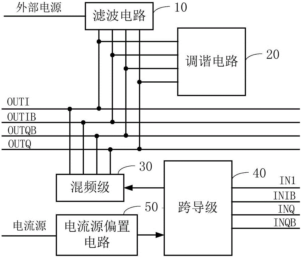
[0051] figure 1 It is a basic structural block diagram of the quadrature input two frequency divider provided by the embodiment of the present invention.

[0052] Such as figure 1 As shown, the quadrature input frequency divider by two provided in this embodiment includes a filter circuit 10 , a tuning circuit 20 , a mixing stage 30 , a transconductance stage 40 and a current source biasing circuit 50 .

[0053] The filtering circuit 10 is used to input an external power supply and output it after filtering.

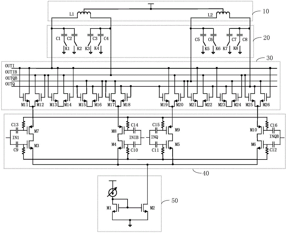
[0054] In a specific application, the filter circuit may use a filter capacitor or an ...


PUM


Abstract

The invention is suitable for the field of frequency dividers, and provides an orthogonal input divide-by-2 frequency divider, which comprises: a filter circuit for inputting an external power supply and performing output after filtering; a tuning circuit connected with an output end of the filter circuit; a mixer stage connected to an output end OUTI, an output end OUTIB, an output end OUTQB and an output end OUTQ of the orthogonal input divide-by-2 frequency divider together with the output end of the filter circuit; a transconductance stage connected with an input end INI, an input end INIB, an input end INQ and an input end INQB of the orthogonal input divide-by-2 frequency divider respectively to input a voltage signal, convert the voltage signal into a current signal and output the current signal to a common source end of the mixer stage; and a current source biasing circuit connected to the common source end of the transconductance stage and enabling the transconductance stage to form a variable current source by injecting an external current source. According to the orthogonal input divide-by-2 frequency divider provided by the invention, the external current source is injected into the current source biasing circuit to enable the transconductance stage to form the variable current source so as to increase the current of the transconductance stage, so that the conversion grain, the degree of linearity and the range of a working frequency of the orthogonal input divide-by-2 frequency divider can be effectively improved.

Description

technical field [0001] The invention belongs to the field of frequency dividers, in particular to a quadrature input two frequency divider. Background technique [0002] Frequency dividers are widely used in the communication field, including quadrature input frequency dividers, phase shift based frequency dividers, etc. [0003] However, the disadvantage of the existing quadrature input frequency divider is that its operating frequency range is limited, and it cannot be well applied to devices with higher requirements on the operating frequency range. Contents of the invention [0004] The object of the present invention is to provide a quadrature input frequency divider by two, which aims to solve the disadvantage of the existing quadrature input frequency divider that its operating frequency range is limited, and it cannot be well suited for applications that require a higher operating frequency range. Device problem. [0005] The present invention is achieved like th...

Claims


Application Information

Patent Timeline
IPC IPC(8): H03K23/00H03K21/02
CPCH03K23/002H03K21/02
Inventor 丁庆傅海鹏马建国
Owner CHINA COMM MICROELECTRONICS TECH CO LTD
Why Eureka
Try Eureka