Zoom climb prevention system for enhanced performance

A technology for controlling variables and vehicles, applied in the field of aircraft control, can solve problems such as difficult control of aircraft

Active Publication Date: 2017-05-03
THE BOEING CO
View PDF11 Cites 2 Cited by
  • Summary
  • Abstract
  • Description
  • Claims
  • Application Information

AI Technical Summary

Problems solved by technology

however, rapid deceleration can cause the current angle of attack to rapidly exceed the desired angle of attack limit and expose the aircraft to difficult control or any of the other undesirable characteristics mentioned above

Method used


Image

  • Zoom climb prevention system for enhanced performance
  • Zoom climb prevention system for enhanced performance
  • Zoom climb prevention system for enhanced performance

Examples


Embodiment Construction

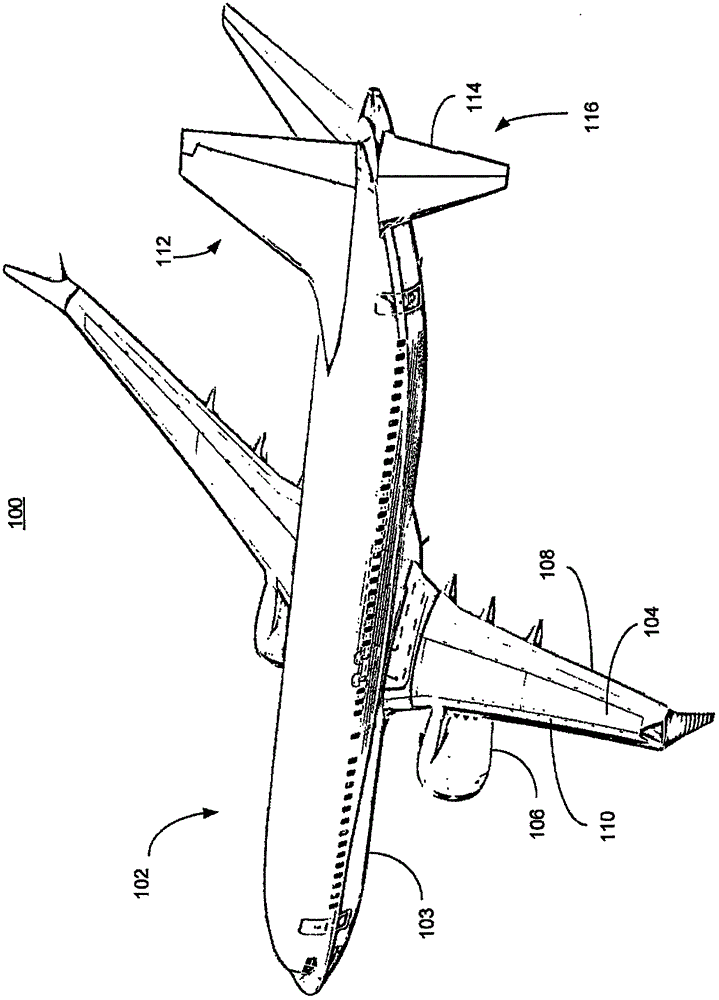
[0024] figure 1 A vehicle 100 is illustrated. exist figure 1 A vehicle 100 , illustrated as an aircraft, has a body 102 including a fuselage 103 and wings 104 . Propulsion unit 106 may be coupled to wing 104 . Wing 104 may also include flaps 108 and leading edge devices 110 that may be deployed in certain situations (eg landing) to increase wing camber thereby causing more lift. Tail 112 includes an elevator 114 as an example of a control surface 116 that affects the pitch attitude of the vehicle in flight.

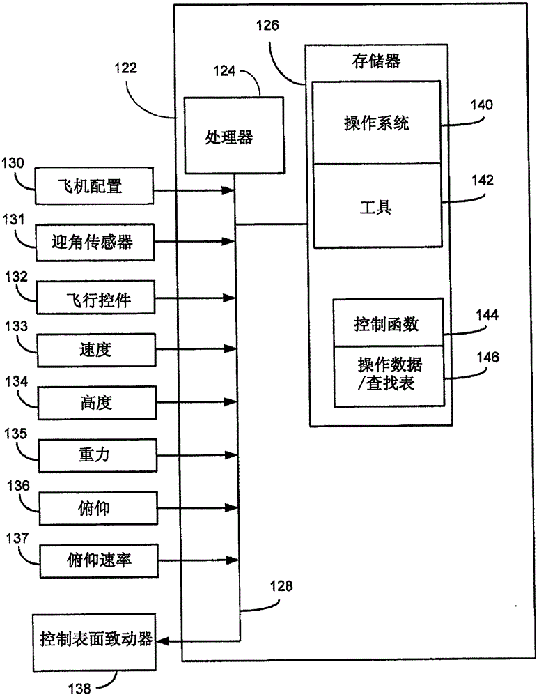
[0025] figure 2 is a block diagram of additional elements of the vehicle 100 . Critical flight digital computer 122 includes processor 124 and memory 126 . A data input / output bus 128 couples processor 124 to memory 126 . Bus 128 also connects critical flight digital computer 122 to various inputs and outputs including, but not limited to, vehicle configuration 130, angle of attack sensor 131, flight controls 132, speed sensor 133, altitude sensor 134, gravity sen...


PUM


Abstract

A vehicle, such as an airplane sets a limit for a control variable used to deflect a control surface. The limit is set as a function of an unfavorable flight condition / target angle of attack and a rate of change of angle of attack so that a pilot control variable command is prevented from exceeding the limit to prevent the vehicle from reaching an unfavorable flight condition and / or exceeding a desired angle of attack limit.

Description

technical field [0001] The present disclosure relates generally to aircraft controls, and more particularly to preventing adverse flight conditions at high angles of attack or beyond desired angles of attack in fly-by-wire aircraft. Background technique [0002] fly-by-wire aircraft attempt to limit the angle of attack to prevent unfavorable flight conditions (UFC) that can occur at high angles of attack, including reduction of lift beyond acceptable limits, high speed buffeting, pitch-up, lateral instability, or these combination of states. These conditions can be avoided by limiting the angle of attack to about at or slightly below the angle of attack beyond which these undesirable characteristics would occur. Angle of attack is closely related to speed (airspeed) and increases inversely with speed. Rapid deceleration, however, can cause the current angle of attack to rapidly exceed the desired angle of attack limit and expose the aircraft to difficult control or any of ...

Claims


Application Information

Patent Timeline
IPC IPC(8): G05B13/04
CPCG05B13/041G05D1/0833B64C13/506B64C13/0425B64C5/02B64C13/503
Inventor H·L·拜尔福尔
Owner THE BOEING CO
Why Eureka
Try Eureka