Method and system for deeply removing dust from flue gas after wet desulfurization

A technology for wet desulfurization and dust removal system, applied in separation methods, chemical instruments and methods, gas treatment, etc., can solve the problem of low dust removal efficiency of flue gas, achieve enhanced heat exchange and demisting effect, low cost, flue gas Evenly distributed effect

Inactive Publication Date: 2017-05-10
AEROSPACE KAITIAN ENVIRONMENTAL TECH CO LTD
View PDF6 Cites 14 Cited by
  • Summary
  • Abstract
  • Description
  • Claims
  • Application Information

AI Technical Summary

Problems solved by technology

[0005] The technical problem solved by the present invention is: aiming at the problem of low dust removal efficiency of flue gas after

Method used


Image

  • Method and system for deeply removing dust from flue gas after wet desulfurization
  • Method and system for deeply removing dust from flue gas after wet desulfurization

Examples


Embodiment

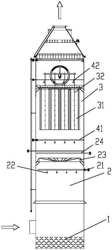
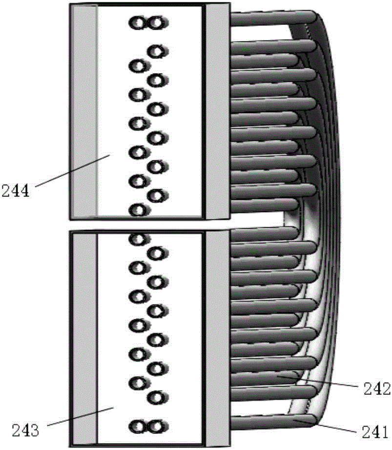
[0034] see figure 1 , the flue gas deep dust removal system shown in the figure is a preferred embodiment of the present invention, mainly including a phase change condensation chamber 2 and a wet electrostatic precipitator 3, the phase change condensation chamber 2 is arranged above the desulfurization absorption tower 1, and inside is arranged The steam distribution pipe 21 is provided with a number of steam nozzles 22, behind the nozzles of the steam distribution pipe 21 there are a swirl plate 23 and a condensing pipe type demister 24, and the wet electrostatic precipitator 3 is arranged in the phase change condensing The exit position of the combining chamber 2 mainly includes an anode plate assembly 31 and a cathode line 32 .

[0035] A flushing device is respectively provided above the condensing demister 24 and the wet electrostatic precipitator 3, wherein a first spray flushing pipe 41 is provided on the condensing demister 24, and a second spray flushing pipe 41 is p...

example 1

[0050] After the flue gas of a coal-fired power plant undergoes wet desulfurization, the dust concentration is 30-50mg / Nm 3 , mainly sulfurous acid droplets, gypsum and PM2.5 and other fine particles, the flue gas directly enters the wet electrostatic precipitator, affected by the nature of the fine particles, it is difficult to achieve efficient dust removal and ultra-low emissions. Using the above-mentioned embodiment, the flue gas after wet desulfurization is nearly saturated or in a state of saturated flue gas. The flue gas first passes through the steam phase change chamber, and is sprayed into the power plant waste steam or secondary steam with a steam saturation of 1.20 through the nozzle to establish a water The supersaturated environment required for the nucleation and condensation of gas on the surface of PM2.5 fine particles, so that the fine particles in the coal-fired flue gas will condense and become larger, and the particle size will increase to more than 20 micr...


PUM

PropertyMeasurementUnit
Particle sizeaaaaaaaaaa

Abstract

The invention discloses a method and system for deeply removing dust from flue gas after wet desulfurization. The method comprises the following steps: performing coagulation on PM2.5 fine particles in flue gas after desulfurization to magnify the particles by steam, and then performing wet electrostatic precipitation. The system for deeply removing dust from flue gas disclosed by the invention comprises a phase change condensing chamber, a condensing defogger and an electrostatic precipitator, wherein the phase change condensing chamber is abutted against the flue gas desulfurization system; a plurality of steam nozzles are arranged in the phase change condensing chamber; the steam nozzles are connected with the steam system through a steam distribution pipe; the electrostatic precipitator is abutted against the outlet of the phase change condensing chamber; and the condensing defogger is arranged on a passage between the phase change condensing chamber and the electrostatic precipitator. The method and system for deeply removing dust from flue gas after wet desulfurization disclosed by the invention effectively solve the problem that the particle sizes of inlet particulate matters of a wet electrostatic precipitator is small, so that the charging is difficult, the dust removal efficiency is improved and deep dust removal is realized.

Description

technical field [0001] The invention relates to a method and system for deep dedusting of flue gas after wet desulfurization, and belongs to the technical field of deep purification of desulfurized flue gas. Background technique [0002] In recent years, the smog weather in my country's cities has become more and more serious, which has seriously affected public health and life. The high content of PM2.5 fine particles is the main cause of smog weather. PM2.5 can be suspended in the atmosphere for a long time, has a large specific surface area, and is easy to enrich toxic substances such as polycyclic aromatic hydrocarbons, viruses and bacteria, as well as trace toxic elements, which has a great impact on human health and the quality of the atmospheric environment. [0003] At present, thermal power plants that use coal-fired thermal power generation are the main sources of dust emissions in my country, although most of these thermal power plants are equipped with electrosta...

Claims


Application Information

Patent Timeline
IPC IPC(8): B01D51/02B01D53/00B01D53/78B01D53/48B03C3/16B03C3/49B03C3/32
CPCB01D51/02B01D53/002B01D53/48B01D53/78B01D2258/0283B03C3/16B03C3/32B03C3/49
Inventor 刘胜强尹涛贺长江何剑雄
Owner AEROSPACE KAITIAN ENVIRONMENTAL TECH CO LTD
Why Eureka
Try Eureka