Assembly welding method of fan-shaped block welding assembly

A welding component and assembly welding technology, which is applied in welding equipment, auxiliary welding equipment, welding/cutting auxiliary equipment, etc., can solve the problems of high repair rate, time-consuming and laborious operation of workers, and large spare parts, so as to improve processing efficiency, The effect of solving the problem of cavity dimensional accuracy

Active Publication Date: 2017-05-10
SHENYANG LIMING AERO-ENGINE GROUP CORPORATION
View PDF7 Cites 10 Cited by
  • Summary
  • Abstract
  • Description
  • Claims
  • Application Information

AI Technical Summary

Problems solved by technology

[0003] Assembling and welding of fan-shaped block welding components at the compressor part usually adopts fixture fixed positioning T-shaped plate and inner flow channel plate to ensure the position accuracy between the two, manual trial assembly of blades, grinding of blades and T-shaped plate and flow channel Install the repaired blades one by one, and use the energy storage spot welding machine to spot weld the blades, the T-shaped plate and the inner runner plate. Since the fixture positioning T-shaped plate and the inner runner plate cannot be adjusted, welding The margin of the front part is large, which leads to uncontrollable margin after welding. Once the gap between the blade and the T-plate and the runner plate is adjusted, the fixture is clamped once. The operation is time-consuming and laborious, and the repair rate after welding is high.

Method used


Image

  • Assembly welding method of fan-shaped block welding assembly
  • Assembly welding method of fan-shaped block welding assembly
  • Assembly welding method of fan-shaped block welding assembly

Examples


Embodiment Construction

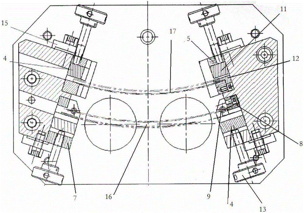
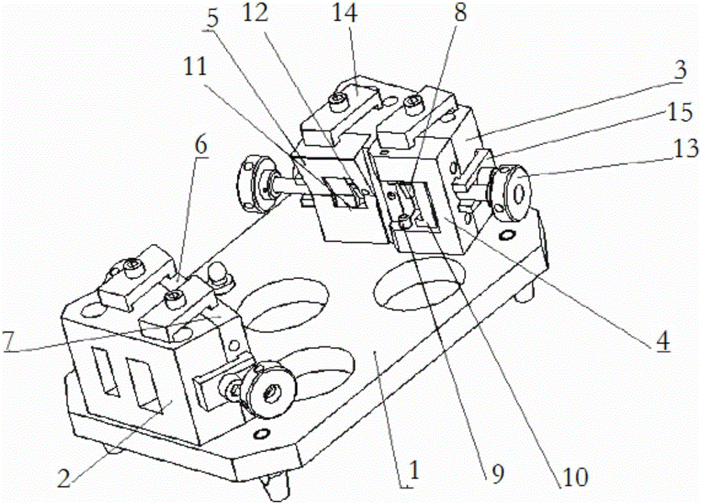
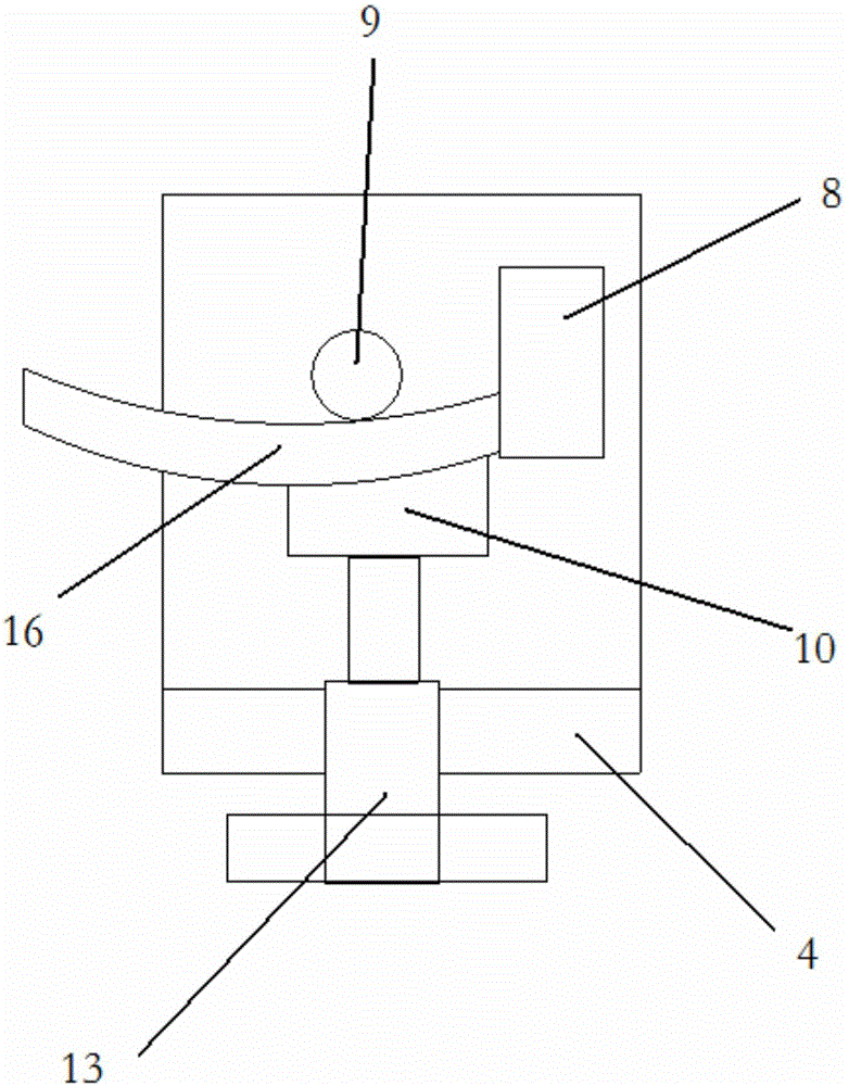
[0035] The present invention is specifically described below in conjunction with accompanying drawing, as Figure 1-Figure 3 As shown, the special fixture includes a bottom plate 1, on which a left angle seat 2 and a right angle seat 3 are fixed, and the side surface of the right angle seat 3 is respectively provided with a T-shaped plate right positioning slide seat 4 and a flow channel plate right The positioning slide 5, the side surface of the left angle seat 2 are respectively provided with a T-plate left positioning slide 7 and a runner plate left positioning slide 6; the top and bottom of the right positioning slide are fixed with T-plate positioning pins 9. The T-shaped plate side positioning block 8 is set on the side, and the T-shaped plate radial pressing block 10 is also set. The T-shaped plate radial pressing block 10 is in contact with the jacking screw, and the jacking screw is fixed on the right positioning slide. In the side wall screw hole of the seat 5; the ...


PUM


Abstract

The invention discloses an assembly welding method of a fan-shaped block welding assembly. By using a clamp positioning adjustable structure, welding deforming control is achieved, gap coping of blades and inner-and-outer templates is convenient, and specifically, the bottom face of a T-shaped plate is positioned through a T-shaped plate right positioning sliding seat, and the side faces of the T-shaped plate are positioned through a T-shaped plate side face positioning block; the T-shaped plate and the positioning sliding seats on the two sides of the T-shaped plate are stored in a fixed base body structure which is composed of a bottom plate, a left angle seat and a right angle seat, the positions are well adjusted, and pressing and fixing are conducted by using an upper face pressing plate and side face pressing plates; and the bottom face and an outer arc of a runner plate are positioned by using a runner plate right positioning sliding seat. The assembly welding method of the fan-shaped block welding assembly has the advantages that (1), machining efficiency is improved; and (2), the economic benefits are improved.

Description

technical field [0001] The invention relates to the technical field of aero-engine manufacturing, in particular to a method for assembling and welding processing of sector block welding components in parts of an aero-compressor. Background technique [0002] The assembly and welding of fan-shaped block welding components has always been a difficult point in the welding and assembly of fan-shaped blocks. It involves the positioning and assembly of six part numbers. Each part has a large margin, and there are 11 blades among them. The blades are between the T-shaped plate and the flow channel plate. , Gap grinding is carried out before assembly, and the precision of the cavity after welding is required to be high (±0.1). [0003] Assembling and welding of fan-shaped block welding components at the compressor part usually uses fixtures to fix the positioning of the T-shaped plate and the inner runner plate to ensure the positional accuracy between the two, manually test the bla...

Claims


Application Information

Patent Timeline
Patent Type & Authority Applications(China)
IPC IPC(8): B23K37/04
CPCB23K37/0443
Inventor 刘建伟曹勇李赞孙玉林付裕
Owner SHENYANG LIMING AERO-ENGINE GROUP CORPORATION
Why Eureka
Try Eureka