Eureka AIR delivers breakthrough ideas for toughest innovation challenges, trusted by R&D personnel around the world.

Magnetic coupling rodless cylinder transmission cutting film device

A rodless cylinder and membrane device technology, which is applied in welding equipment, laser welding equipment, metal processing, etc., can solve the problems of film waste, film cutting edge, easy to be scratched, plate surface damage, etc., to reduce the occupied length , Reduce power consumption and occupy a small space

Inactive Publication Date: 2017-05-10
无锡昊康通用机械有限公司
View PDF6 Cites 6 Cited by
  • Summary
  • Abstract
  • Description
  • Claims
  • Application Information

AI Technical Summary

Problems solved by technology

[0003] At present, more than 90% of the market uses the lifting of the thermal resistance wire to cut the film and fuse the film between two uneven plates. This method is simple in principle, convenient and effective, but the disadvantages are obvious: first, the edge of the film after melting Irregular wavy shape, the warped film at the edge of the plate will cause the film to be easily scratched, resulting in partial exposure of the surface of the plate, which will cause a certain degree of damage to the surface of the plate during stacking and transportation, affecting the quality of the product; secondly , a part of the fused film will stick to the thermal resistance wire, which will also cause the film to warp during the film cutting process; again, the thermal resistance wire generally needs to be installed with a cutting film in order to prevent the thermal resistance wire from touching the board during the pressing process. Adjust the spacing to 5MM or more, resulting in waste of the film and unsightly cutting edge, which is unacceptable to high-end customers; in addition, the material of the film is generally PVC plastic, which is a poor conductor of heat. After accumulating on the surface, it will cause insufficient heat conduction of the thermal resistance wire, resulting in inability to continue working

Method used


Image

  • Magnetic coupling rodless cylinder transmission cutting film device
  • Magnetic coupling rodless cylinder transmission cutting film device

Examples


Embodiment Construction

[0020] The present invention will be described in further detail below in conjunction with accompanying drawing description and specific embodiment:

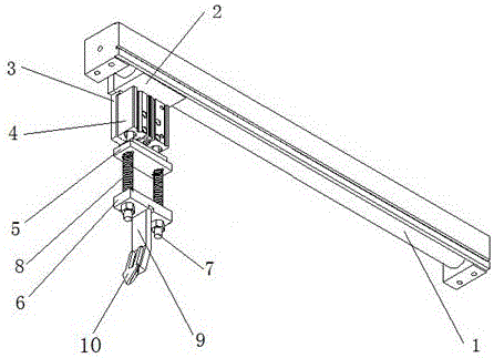
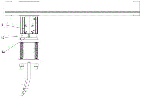
[0021] like figure 1 and figure 2 As shown, a magnetically coupled rodless cylinder transmission film cutting device includes a horizontally magnetically coupled rodless cylinder 1 on which a cylinder slide 2 is slidably installed, and also includes a T-shaped fixing plate 3. Vertical movement cylinder 4, screw rod 7, first cylinder fixed plate 5, second cylinder fixed plate 6, spring 8, film cutting knife rest 9 and film cutting knife 10, described vertical movement cylinder 4 passes T-shaped The fixed plate 3 is vertically installed below the cylinder slide table 2, and the vertical motion cylinder 4 includes a cylinder block 41, a push rod 43 positioned at the bottom center of the vertical motion cylinder block and a piston rod 42 positioned at the bottom two ends of the vertical motion cylinder block , the push rod 43 and...


PUM


Abstract

The invention relates to a magnetic coupling rodless cylinder transmission cutting film device, which includesa magnetic couplinghorizontal rodless cylinder.The magnetic couplinghorizontal rodless cylinder is slidably provided with a cylinder slide unit.A vertical movable cylinder is vertically installed below the cylinder slide unit througha T-shaped fixed plate. The vertical movable cylinder includes a cylinder block, a push rod at the bottom center of the verticalmovable cylinder blockand a piston rod at two ends in the bottom of the vertical movable cylinder block. The push rod and the piston rod can move up and down along the vertical movable cylinder block. The other end of the piston rod and the push rod are fixedly installed on the top of a first cylinder fixed plate.A screw rod is symmetrically installed on two ends at the bottom of the first cylinder fixed plate.A second cylinder fixed plate is installed at the bottom of the screw rod. A spring is installed outside the screw rod.A cutting film knife rest is welded on the middle of the bottom of the secondcylinder fixed plate.A cutting film knife is installed at the lower end of the cutting film knife rest. The cutting film device can carry out automatically cutting film at an accurate position, and realize the neat and orderly cross-section. The work of cutting film can be incessantly finished on the automatical production line, which improvesthe operating efficiency. The cutting film device is also simple in the structure, and easy to be generalized and used.

Description

technical field [0001] The invention relates to a film cutting device driven by a rodless cylinder, in particular to a magnetic coupling type rodless cylinder driven film cutting device. Background technique [0002] With the continuous improvement of science and technology and people's living standards, sheet metal products have been widely used in daily production and life. At present, applying film to the surface of sheet metal products has become a very popular process for protecting the processed surface; however, after the surface of sheet metal is attached with a film, it is usually accompanied by a simple and cumbersome process operation- cut film. For narrow flat panels, at least one worker needs to hold a cutting knife to complete film cutting; for wide flat panels, at least two to three workers need to hold cutting knives to complete the film cutting action; especially the film sticking speed is higher In some cases, more manpower is required. [0003] At prese...

Claims


Application Information

Patent Timeline
Patent Type & Authority Applications(China)
IPC IPC(8): B26D7/26B26D5/12B23K26/38B23K26/70
CPCB26D7/2628B23K26/38B23K26/70B26D5/12
Inventor 陈中胜陈虎
Owner 无锡昊康通用机械有限公司
Why Eureka
Eureka Blog
Learn More