Eureka AIR delivers breakthrough ideas for toughest innovation challenges, trusted by R&D personnel around the world.

Cutting method and application method of high-temperature protective film for bonding

A cutting method and technology of protective film, applied in laser welding equipment, electrical components, circuits, etc., can solve the problems of inability to grasp the size, difficulty, reduce the UPH of the machine, etc. The effect of quality and performance

Inactive Publication Date: 2018-09-04
浙江华越芯装电子股份有限公司
View PDF7 Cites 0 Cited by
  • Summary
  • Abstract
  • Description
  • Claims
  • Application Information

AI Technical Summary

Problems solved by technology

[0003] 1. The cutting speed is slow. It is necessary to manually cut a piece of film into small squares of about 1.5mm~3.0mm, which usually takes 30 minutes to 1 hour;
[0004] 2. The cutting effect is poor, the square to be cut is only about 2mm, the size cannot be grasped manually, the size is inconsistent, and the blade is worn out, resulting in burrs on the edge of the square
[0005] 3. The high temperature protective film wears a lot. If you cut a piece of film by hand, usually 20%~40% of the area cannot be used.
Not only can it not improve the first welding aspects such as ball extrusion and non-sticking from other aspects, but also can not meet the requirements while reducing the UPH of the machine
In addition, it is also difficult to process small PAD products; in actual production, it is impossible to process without relying on the film

Method used


Image

  • Cutting method and application method of high-temperature protective film for bonding
  • Cutting method and application method of high-temperature protective film for bonding
  • Cutting method and application method of high-temperature protective film for bonding

Examples


Embodiment Construction

[0033] In order to make the technical means of the present invention and the technical effects that can be achieved more clearly and more completely disclosed, an embodiment is provided hereby, and the following detailed description is given in conjunction with the accompanying drawings:

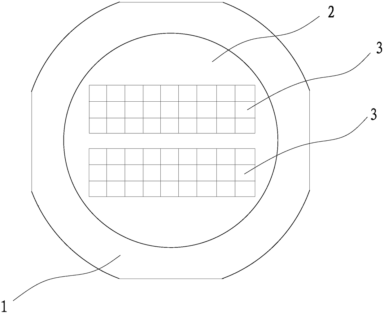
[0034] Such as figure 1 as shown, figure 1 It is a schematic diagram of the combination of the high-temperature protective film 3, the blue film 2 and the thin iron plate 1 after cutting by the cutting method of the present invention. A cutting method of the high-temperature protective film 3 for bonding in this embodiment includes the following steps:

[0035] Step (1) Prepare a flat thin iron plate 1;

[0036] Step (2) Paste the blue film 2 for scribing on the thin iron plate 1 evenly;

[0037] Step (3) Attach the high temperature protective film 3 to be cut evenly on the blue film 2 for scribing;

[0038] Step (4) Place the thin iron plate 1 with the blue film 2 and the high temperatur...


PUM


Abstract

The invention discloses a cutting method and an application method of a high-temperature protective film for bonding and relates to the technical field of integrated circuit packaging. The cutting method of the high-temperature protective film for bonding comprises the steps that firstly, a flat sheet iron plate is prepared; secondly, a blue film for scribing is smoothly pasted to the sheet iron plate; thirdly, the high-temperature protective film needing to be cut is smoothly pasted to the blue film for scribing; fourthly, the sheet iron plate pasted with the blue film and the high-temperature protective film is put at the position to be scribed of a scribing machine; fifthly, the position of a blade of the scribing machine is adjusted or the parameters of the scribing machine are set; and sixthly, the high-temperature protective film is cut into 1.5*1.5 mm or 2.0*2.0 mm square blocks. The application method of the high-temperature protective film for bonding comprises the steps thatfirstly, before pasting, grooves are checked; secondly, the cut high-temperature protective films are put into the grooves of a heating bottom plate of an integrated circuit; and thirdly, the high-temperature protective films are smoothly pasted to the grooves. According to the film cutting method, operation is easy, and the speed is high; and the film cutting effect is good, and the problems of burrs, inconsistent sizes and the like do not exist.

Description

technical field [0001] The invention relates to a cutting method and a using method of a high-temperature protective film for bonding, and belongs to the technical field of integrated circuit packaging. Background technique [0002] Before the bonding operation of the integrated circuit packaging process, due to the gap between the lead frame and the equipment bottom plate, the product quality is affected during the bonding and the output rate of the equipment is low, so it is necessary to carry out the heating block groove of the bonding base. Film sticking is widely used in bonding process SOP16-8R(60*60), SOP8-8R(60*60) and other small PAD area products. In the past, the manual cutting of the film had the following disadvantages: [0003] 1. The cutting speed is slow. It is necessary to manually cut a piece of film into small squares of about 1.5mm~3.0mm, which usually takes 30 minutes to 1 hour; [0004] 2. The cutting effect is poor, the square to be cut is only about...

Claims


Application Information

Patent Timeline
IPC IPC(8): B23K26/38B23K26/70B26D1/00H01L21/48
CPCB23K26/38B23K26/70B23K26/702B26D1/00H01L21/48H01L21/4885
Inventor 杨建尧章建声
Owner 浙江华越芯装电子股份有限公司
Why Eureka
Eureka Blog
Learn More