

Air film cooling hole structure
A technology of air film cooling and air film hole, which is applied in the direction of supporting elements of blades, engine elements, machines/engines, etc., which can solve the problem that the cooling air flow is easy to rush into the mainstream, the high blowing ratio is easy to blow off the wall, and the exit area of the cylindrical hole Small and other problems, to achieve the effect of simple structure, low price, and increase cooling efficiency
- Summary
- Abstract
- Description
- Claims
- Application Information
AI Technical Summary
Problems solved by technology
Method used
Image

Examples
Embodiment 1
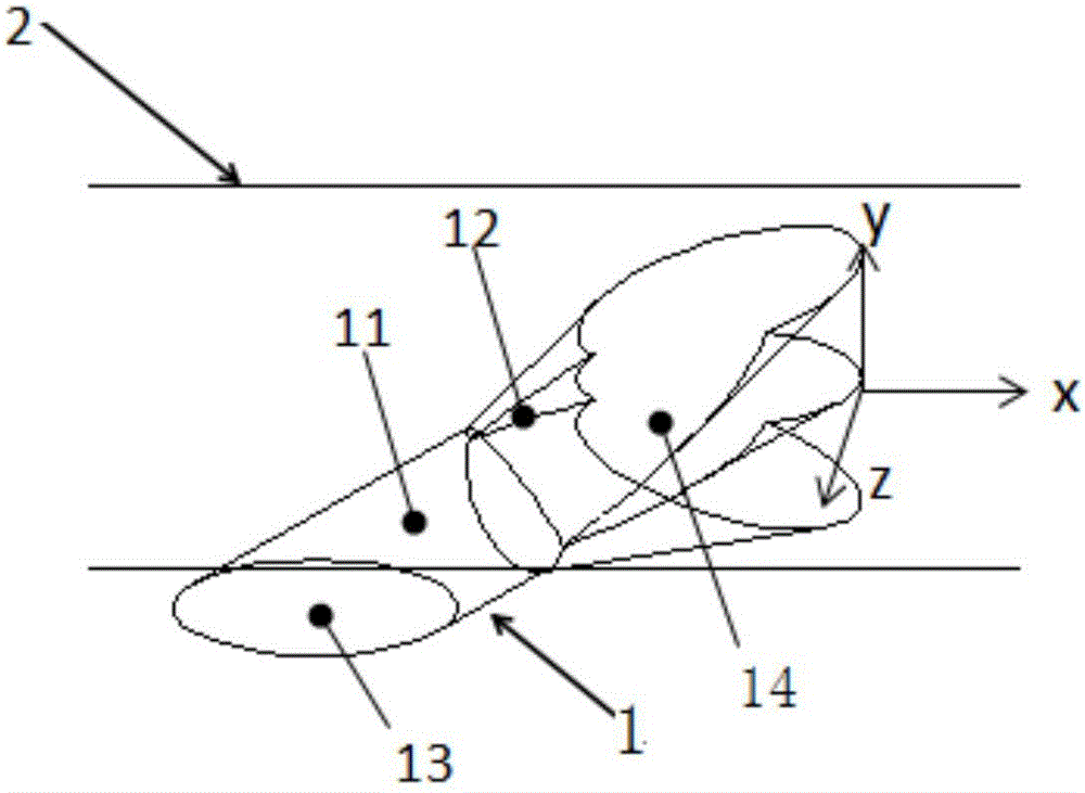
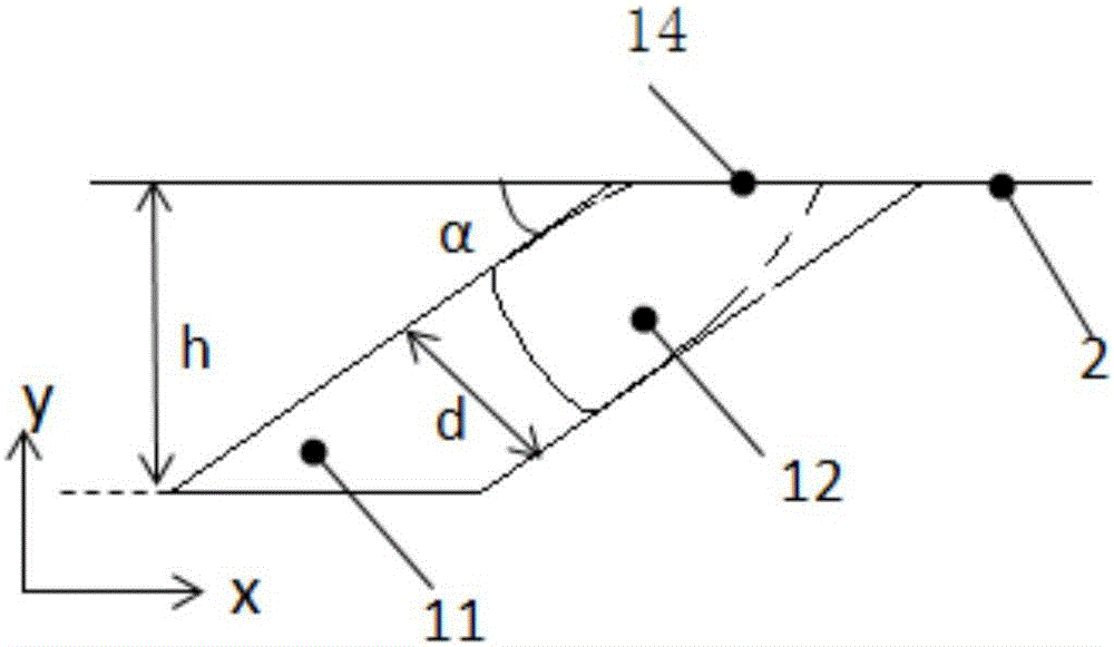
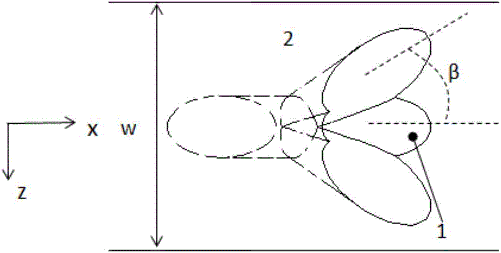
[0039] The air film cooling hole type structure of this embodiment (referring to Figure 1-4) comprises air film hole 1 and wall surface 2, and the outlet of air film hole is positioned at the upstream area of wall surface, and described air film hole 1 comprises cylinder section 11 and expansion section 12, and one end of cylinder section is cold air inlet 13, and the cylinder section The other end is connected to one end of the expansion section, and the other end of the expansion section is the outlet 14 of the gas film hole. The expansion section 12 is composed of a middle hole 121 and two expansion holes 122, and the middle hole communicates with each expansion hole. In the top view of the wall, the two expansion holes are arranged axisymmetrically with the middle hole as the axis, that is, the outlet of the gas film hole is axisymmetric in the transverse direction of the wall, and the angle β between each expansion hole and the central axis of the middle hole is 30 °. ...
Embodiment 2
[0047] The air film cooling hole type structure of this embodiment (referring to Figure 10 ) each part composition and position relation are the same as embodiment 1, the difference is that expansion hole 122 holes are quadrangular prisms, and the angle β between each expansion hole and the central axis of the middle hole is 40 °, the expansion hole and the middle The pore diameter ratio was 0.5.
Embodiment 3
[0049] The air film cooling hole type structure of this embodiment (referring to Figure 11 The composition and positional relationship of each part of ) is the same as that of Embodiment 1, the difference is that the middle hole of the expansion section is a tapered conical hole, which can allow more cooling air to flow through the expansion holes on both sides, and can increase the lateral cooling effect of the wall surface , and due to the contraction of the middle hole, the spanwise cooling effect at the centerline of the wall will not be reduced, and the ratio of the diameter of the expansion hole to the middle hole is 0.85.
[0050] What is not mentioned in the present invention is applicable to the prior art.
PUM
 Abstract
Description
Claims
Application Information