
A chain type rotor hydraulic motor

A hydraulic motor and chain technology, applied in the field of chain-type rotor hydraulic motors, can solve the problems of reducing the mechanical efficiency of the hydraulic motor, reducing the volumetric efficiency of the hydraulic motor, and the arrangement of the plunger is not compact enough to achieve high torque, improve mechanical efficiency and reliability. high effect

Inactive Publication Date: 2018-06-29
HENAN UNIV OF SCI & TECH
View PDF6 Cites 0 Cited by
  • Summary
  • Abstract
  • Description
  • Claims
  • Application Information

AI Technical Summary

Problems solved by technology

However, due to the large radial size of the radial plunger hydraulic motor, the arrangement of the plunger is not compact enough, and the structure is complex, and the self-priming ability is poor. The distribution shaft is affected by the radial unbalanced pressure, and the diameter of the distribution shaft must be made larger. To avoid excessive deformation; at the same time, the gap between the distribution shaft and the bush after wear cannot be automatically compensated, and the leakage is large, which reduces the volumetric efficiency of the hydraulic motor and reduces the mechanical efficiency of the hydraulic motor

Method used


Image

  • A chain type rotor hydraulic motor
  • A chain type rotor hydraulic motor
  • A chain type rotor hydraulic motor

Examples


Embodiment Construction

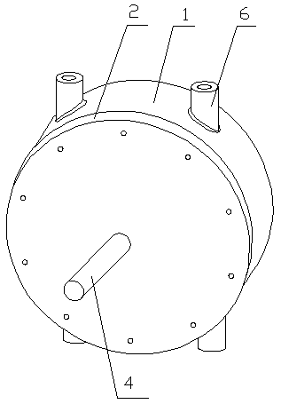
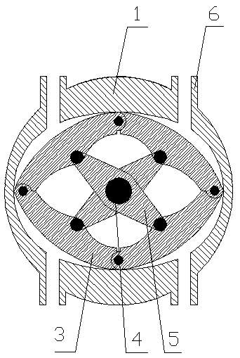
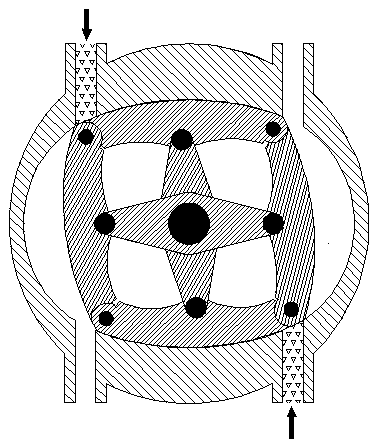
[0020] Such as figure 1 and figure 2 As shown, a chain-type rotor hydraulic motor of the present invention includes a cylinder body 1 and a chain-type rotor 5 arranged in the cylinder body 1, and the chain-type rotor 5 includes four arc-shaped chains 3 and a center shaft 4. The four chains 3 are hinged end to end to form a ring, and a hinged link 5 with a through hole in the center is provided between the two opposite chains 3, and the two ends of the hinged link 5 are respectively hinged on the opposite two chains. The middle part of the chain 3, the hinge connection of four chains 3 and two articulated connecting rods 5 jointly form the torque transmission mechanism of the present invention. The middle part of the central axis 4 is arranged in the through holes on the two hinged connecting rods 5 and is fixedly connected with one of the hinged connecting rods 5. In this embodiment, the central axis 4 and one of the hinged connecting rods 5 pass through The spline structur...


PUM


Abstract

The invention relates to the technical field of hydraulic motors and discloses a hydraulic motor with a chain type rotor. The hydraulic motor with the chain type rotor comprises a cylinder and the chain type rotor. The chain type rotor comprises four arc-shaped chains and a central shaft, the four chains are hinged end to end to form a ring, a hinged connecting rod provided with a through hole at the center is formed between every two opposite chains, and the middle portion of the central shaft is arranged in the through holes of the two hinged connecting rods and is fixedly connected to one of the hinged connecting rods; an inner molded line of the cylinder is a discrete fitted elliptical curve of the arc-shaped surfaces of the four chains, four volume cavities which are partitioned are separately formed between the inner wall of the cylinder and the arc-shaped surfaces of the four chains, four oil pipes are arranged along the circumference of the cylinder at intervals, and the volumes of the volume cavities change by virtue of oil injection and oil discharge, so that the chain type rotor generates a turning moment and drives the central shaft to rotate. Compared with a conventional hydraulic motor, the hydraulic motor with the chain type rotor is compact in structure and small in size, can generate higher torque and rotating speed, and can meet the requirements of an engineering load on the torque and the rotating speed in most instances.

Description

technical field [0001] The invention relates to the technical field of hydraulic motors, in particular to a chain-type rotor hydraulic motor. Background technique [0002] The hydraulic motor is an actuator that converts pressure energy into mechanical energy and acts externally. The main forms are gear type, screw type, vane type and axial plunger type. [0003] Gear-type and screw-type hydraulic motors cannot generate large torque due to poor sealing, low volumetric efficiency, and high input oil pressure. And the instantaneous speed and torque change with the position of the meshing point, so the gear hydraulic motor is only suitable for high-speed and low-torque occasions. It is generally used in construction machinery, agricultural machinery and mechanical equipment that does not require high torque uniformity. [0004] The blades of the vane hydraulic motor should be placed radially. In order to make the root of the blade always have pressure oil, a one-way valve sho...

Claims


Application Information

Patent Timeline
Patent Type & Authority Patents(China)
IPC IPC(8): F03C2/00
CPCF03C2/00
Inventor 曹付义李豪迪李金龙崔梦凯雷彦龙
Owner HENAN UNIV OF SCI & TECH
Learn More