Integral type multi-way valve and working method thereof

An integral, multi-way valve technology, used in the field of multi-way valves, can solve the problems of increasing pipeline layout, throwing trash cans, and large energy loss, reducing pipeline layout, avoiding bucket throwing, and easy mass production. Effect

Inactive Publication Date: 2017-05-10
HUNAN HONGHUI TECH
View PDF12 Cites 0 Cited by
  • Summary
  • Abstract
  • Description
  • Claims
  • Application Information

AI Technical Summary

Problems solved by technology

[0004] 1. The speed of the trash can is uncontrollable when it is lifted and dumped, and the trash can is smashed, especially when the garbage is heavy and the weather is cold;
[0005] 2. When the push shovel multi-stage oil cylinder completes the compression action and retreats, the back pressure is too high, the energy loss is large, the car is held back, and the flame is turned off in s

Method used


Image

  • Integral type multi-way valve and working method thereof
  • Integral type multi-way valve and working method thereof
  • Integral type multi-way valve and working method thereof

Examples


Embodiment 1

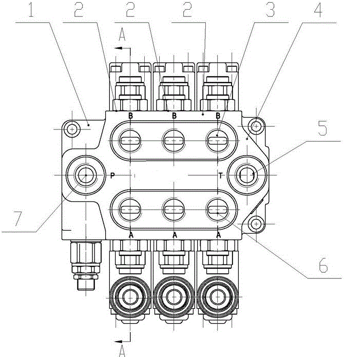
[0037] Such as figure 1 , 2 As shown, an integral multi-way valve includes an oil inlet valve unit 1, a plurality of working valve units 2 and an oil return valve unit 4; the plurality of working valve units 2 are arranged on the oil inlet valve unit 2 and Between the oil return valves 4; the oil inlet valve 1, the working valve 2 and the oil return valve 4 are integral structures; the oil inlet valve 2 is provided with an oil inlet P7, and the oil return valve The connection 4 is provided with an oil return port T5; each of the plurality of working valve connections 2 is provided with two working oil ports A6, B3; it is characterized in that: the working valve connection 2 is provided with a hydraulic lock 8, pressure compensation flow control The valve 11 and the reversing valve stem assembly 13 are arranged sequentially from top to bottom.

Embodiment 2

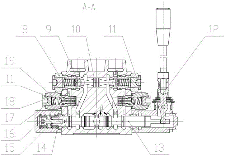
[0039] On the basis of Embodiment 1, a valve cavity is set in the working valve unit 2, and the hydraulic lock 8, the hydraulic lock control push rod 10, the pressure compensation flow control valve 11, and the reversing valve stem assembly 13 are all set in the valve cavity. Inside, the end cover 14 and the reversing operating mechanism 12 are placed outside the valve cavity through screw connection.

Embodiment 3

[0041] On the basis of Embodiment 1, the pressure-compensated flow control valve 11 is connected to the valve chamber through the thread on the valve sleeve 19, the throttle plug 15 is connected to the valve core 16 through the thread, and the valve core 16 is sleeved in the valve sleeve 19 , and withstand one end of the spring 17, and the other end of the spring 17 is provided with a plug 18.

[0042] Further, the valve core 16 is provided with an annular groove g, and the valve sleeve 19 is provided with a small hole h.


PUM


Abstract

The invention relates to an integral type multi-way valve. The integral type multi-way valve comprises an oil inlet valve joint (1), a plurality of working valve joints (2) and an oil return valve joint (4), wherein the plurality of working valve joints (2) are arranged between the oil inlet valve joint (1) and the oil return valve joint (4); the oil inlet valve joint (1), the working valve joints (2) and the oil return valve joint (4) form an integral type structure; the oil inlet valve joint (1) is provided with an oil inlet P(7), and the oil return valve joint (4) is provided with an oil return opening T(5); and each of the plurality of working valve joints (2) is provided with two working oil openings A(6) and B(3). The integral type multi-way valve is characterized in that a hydraulic lock (8), a pressure compensation flow control valve (11) and a reversing valve rod assembly (13) are sequentially arranged in each working valve joint (2) from the top to the bottom. The integral type multi-way valve has the advantages that flow and pressure distribution is reasonable, energy is saved, emission is reduced, and the phenomena of barrel tossing, engine extinguishing and cylinder collision are effectively solved.

Description

technical field [0001] The invention relates to a multi-way valve, in particular to an integral multi-way valve. Background technique [0002] Among the many sanitation machines, the side-mounted garbage compression truck automatically dumps the garbage by lifting the garbage can through the pull rod, which can conveniently collect the garbage in the roadside garbage can into the garbage compartment, and compress the garbage into pieces through the rear compression device for transportation. One person can complete the operation, convenient, fast, high efficiency, saving labor, saving garbage volume, no secondary pollution, wide application range, and a high market penetration rate at present. [0003] The side-mounted garbage compression transport vehicle system is powered by the vehicle's own engine, and is connected to the quantitative pump through the power take-off to provide high-pressure oil source for the system. Through the multi-way valve reversing, the garbage can...

Claims


Application Information

Patent Timeline
IPC IPC(8): F15B13/02
CPCF15B13/02
Inventor 吴光镇
Owner HUNAN HONGHUI TECH
Why Eureka
Try Eureka