Supercharge Your Innovation With Domain-Expert AI Agents!

A thin film differential pressure core

A differential pressure, thin film technology, applied in the measurement of fluid pressure, fluid pressure measurement through mechanical components, elastic deformation meter type fluid pressure measurement, etc., can solve resistance drift, can not directly measure water vapor, water or other corrosive liquids Pressure, measurement error, etc.

Active Publication Date: 2020-04-03
48TH RES INST OF CHINA ELECTRONICS TECH GROUP CORP
View PDF6 Cites 0 Cited by
  • Summary
  • Abstract
  • Description
  • Claims
  • Application Information

AI Technical Summary

Problems solved by technology

If the thin film chip resistor is not properly protected, it is easy to absorb water vapor or oxygen to cause resistance drift and cause measurement errors. Therefore, the surface and lead wires of the thin film chip resistor cannot directly measure the pressure of water vapor, water liquid or other corrosive liquids. Cannot be used to measure liquid differential pressure without protection

Method used


Image

  • A thin film differential pressure core

Examples


Embodiment Construction

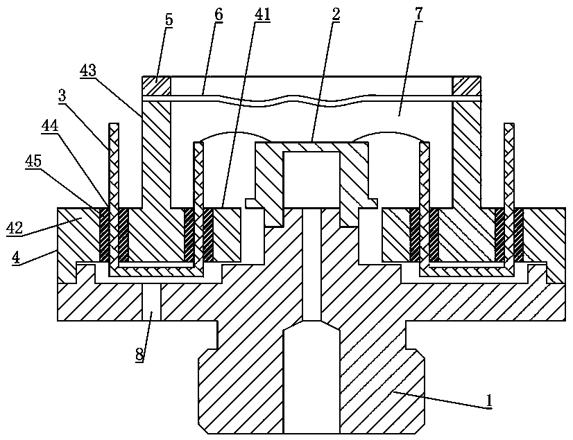
[0020] The present invention will be further described below in conjunction with the accompanying drawings and specific embodiments.

[0021] Such as figure 1 As shown, the film differential pressure core of this embodiment includes a tube base 1, a chip 2, a lead post 3 and a lead bracket 4, the chip 2 is installed in the middle of the tube base 1, and the lead bracket 4 includes an inner ring 41 and an outer ring 42 And the ring 43, the outer peripheral side of the outer ring 42 is sealed with the socket 1, the ring 43 is located between the inner ring 41 and the outer ring 42 and protrudes from the front surface of the chip 2, and the end of the ring 43 is equipped with a pressure ring 5 A corrugated diaphragm 6 is sealed between the end of the ring 43 and the pressure ring 5, wherein the pressure ring 5 cooperates with the end of the ring 43 to seal and install the corrugated diaphragm 6; the corrugated diaphragm 6, the tube seat 1 and the lead bracket 4 enclosing and for...


PUM


Abstract

The present invention discloses a thin film differential pressure core. The thin film differential pressure core comprises a tube holder, a chip, a lead column and a lead bracket; the chip is mounted on the tube holder; the lead bracket comprises an inner ring, an outer ring and an annulus; the outer peripheral side of the outer ring is connected with the tube holder in a sealed manner; the annulus is located between the inner ring and outer ring; the end surface of the upper end of the annulus is higher than the front surface of the chip; an end portion of the annulus is provided with a pressing ring; a corrugated diaphragm is installed between the end portion of the annulus and the pressing ring; a sealed oil storage cavity into which silicone oil can be injected is formed among the corrugated diaphragm, the tube holder and the lead bracket; an oil injection hole communicated with the sealed oil storage cavity is formed in the lead bracket or the tube holder; wire holes are formed in the inner ring and the outer ring; one end of the lead column is connected with the chip; and the other end of the lead column is bent by the wire hole of the inner ring, and is led out through the wire hole of the outer ring. The thin film differential pressure core of the invention has the advantages of simple structure and good protective performance, is suitable for harsh environments.

Description

technical field [0001] The invention mainly relates to the technical field of pressure measurement, in particular to a film differential pressure core body. Background technique [0002] At present, the differential pressure sensor is basically packaged with a silicon piezoresistive chip. The silicon piezoresistive chip is pasted on the tube base through silica gel, and both ends of the tube base are encapsulated in silicone oil. It is difficult for silicon piezoresistive cores to withstand large-scale pressures above 35MPa. The silicon piezoresistive chip is fixed by pasting, and the pressure at the low-pressure end cannot exceed 500KPa at the high-pressure end, otherwise it will easily cause leakage. The silicon piezoresistive core has poor temperature characteristics and is difficult to compensate. It is mainly used for pressure measurement in the range of -40°C to 125°C, and the measurement temperature drift is large in high temperature environments above 150°C. The th...

Claims


Application Information

Patent Timeline
Patent Type & Authority Patents(China)
IPC IPC(8): G01L7/02G01L9/06G01L19/06
CPCG01L7/02G01L7/022G01L19/0627
Inventor 何迎辉金忠
Owner 48TH RES INST OF CHINA ELECTRONICS TECH GROUP CORP
Features
  • R&D
  • Intellectual Property
  • Life Sciences
  • Materials
  • Tech Scout
  • Unparalleled Data Quality
  • Higher Quality Content
  • 60% Fewer Hallucinations
Learn More