Virtual reality helmet distortion complete machine detection method and device

A virtual reality and helmet technology, applied in the field of virtual reality, can solve the problems of inability to detect the distortion parameters of virtual reality helmets, and achieve the effects of improving accuracy and adaptability, facilitating setting, and preventing interference.

Inactive Publication Date: 2017-05-10
VR TECH HLDG LTD
0 Cites 4 Cited by

AI-Extracted Technical Summary

Problems solved by technology

[0003] In order to solve the defect that the current virtual reality equipment cannot detect the distortion parameters of the vir...

Method used

Compared with the prior art, the present invention utilizes observation unit 2 to simulate the observation mode of human eyes to observe the image information played by the virtual reality helmet 12 to be detected, and establishes the point on the display screen 16 of the virtual reality helmet 12 to be detected The mapping relationship between the position and the observation position of the observation eyepiece 23, using the corresponding relationship to fit the distortion function, provides a method for detecting the distortion function of the virtual reality helmet 12 to be detected. The observation unit 2 observes the light emitted by the virtual reality helmet 12 to be detected by simulating the angle of view of the human eye, which is conducive to better simulating the observation method of the human eye, and the detection result is also closer to the image actually seen by the human eye, improving accuracy and adaptability. Using the method of displaying the horizontal scale bar provides a method of establishing a corresponding relationship between functions, and can easily obtain the coordinates of the viewing point corresponding to the screen position. The scale is displayed in green to help the image unit 3 to identify it. The light-shielding dev...

Abstract

The invention provides a virtual reality helmet distortion complete machine detection device comprising a detection unit, an observation unit, an image unit and a processing unit. The detection unit comprises a virtual reality helmet to be detected and a fixing structure. The image unit is electrically connected with the observation unit and the processing unit. The virtual reality helmet to be detected comprises display screens and optical lenses. The display screens and the optical lenses are oppositely arranged. The observation unit comprises a light shading device and an observation eye lens. The light shading device is detachably fixed on the observation eye lens. The light shading device comprises a slit. Compared with the devices in the prior art, image information played by the virtual reality helmet to be detected is observed by using the observation mode simulating human eyes, the corresponding relationship of the position of the point on the display screens of the virtual reality helmet to be detected and the observation position of the observation eye lens is established, fitting of a distortion function is performed by using the corresponding relationship and thus a method of the distortion function for detecting the virtual reality helmet to be detected is provided.

Application Domain

Technology Topic

Human eyeObservation unit +5

Image

  • Virtual reality helmet distortion complete machine detection method and device
  • Virtual reality helmet distortion complete machine detection method and device
  • Virtual reality helmet distortion complete machine detection method and device

Examples

  • Experimental program(1)

Example Embodiment

[0030] In order to solve the defect that current virtual reality equipment cannot detect lens distortion parameters, the present invention provides a method and device for detecting distortion of virtual reality helmets.
[0031] In order to have a clearer understanding of the technical features, purposes and effects of the present invention, the specific implementation manners of the present invention will now be described in detail with reference to the accompanying drawings.
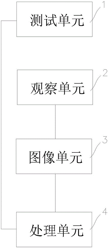
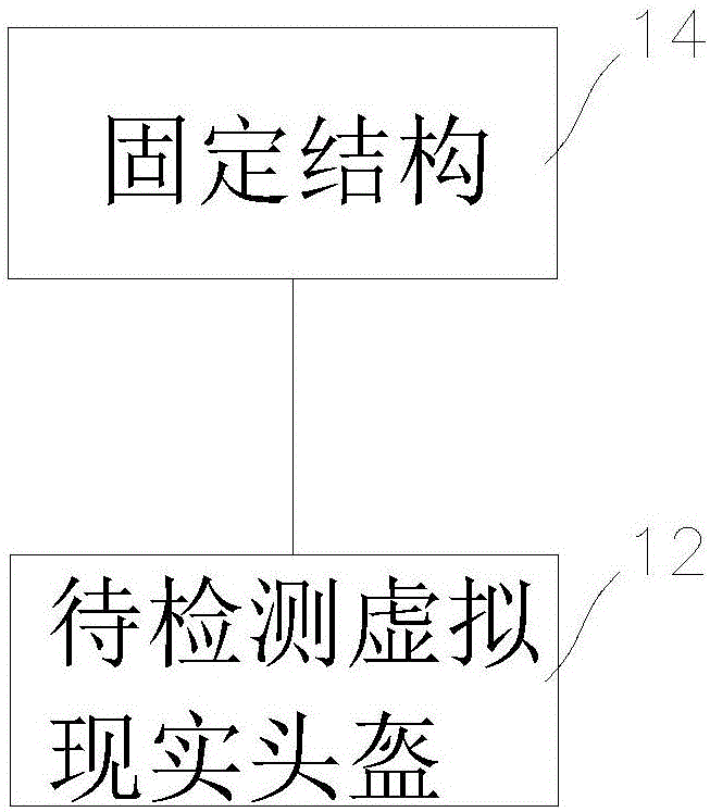
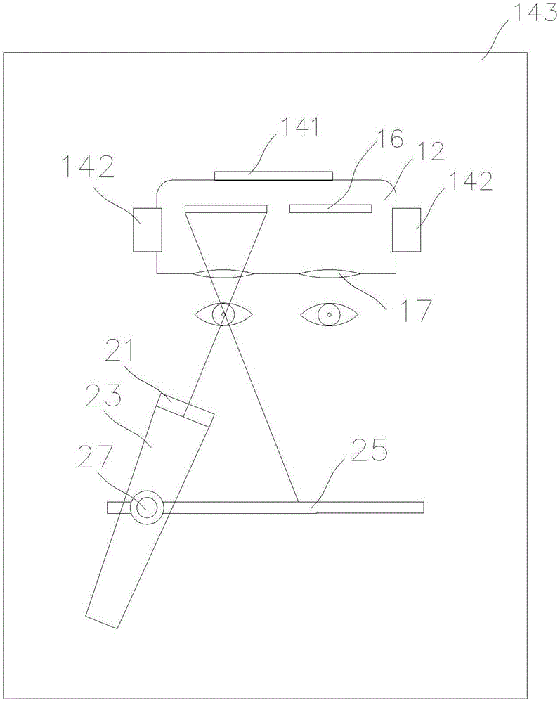
[0032] see figure 1 — figure 2 , the virtual reality helmet distortion detection device of the present invention includes a detection unit 1 , an observation unit 2 , an image unit 3 and a processing unit 4 . Wherein, the detection unit 1 includes a virtual reality helmet 12 to be detected and a fixing structure 14 , and the virtual reality helmet 12 to be detected is detachably fixed on the fixing structure 14 . The image unit 3 is electrically connected to the observation unit 2 , and the processing unit 4 is electrically connected to the image unit 3 . The observation unit 2 observes the detection unit 1 by taking images, the observation unit 2 can take images of the detection unit 1, and transmits the taken images to the image unit 3 for processing, and the image unit 3 can process the images taken by the observation unit 2 , and transmit the processing result to the processing unit 4 for processing, the processing unit 4 performs processing according to the data transmitted by the image unit 3, and fits the distortion function according to the data processing result. Since most of the current virtual reality helmets use axisymmetric optical systems, for axisymmetric optical systems, the distortion parameters of the entire optical system can be calculated mathematically by measuring the distortion parameters of the horizontal central axis, so we can The distortion parameters of its horizontal central axis are detected. The processing unit 4 is electrically connected to the detection unit 1. During use, the processing unit 4 can command the display screen 16 to display a green scale, and the image unit 3 detects that the display information of the virtual reality helmet 12 to be detected reaches the observation unit 2 after being distorted. image, and read the scale information in the image, the image unit 3 transmits the read scale information to the processing unit 4, and the processing unit 4 stores the corresponding relationship between the position of the scale and the position of the observation unit 2. The observation unit 2 moves to the next observation position for observation, and the image unit 3 transmits the corresponding relation of the observation point to the processing unit 4 . After multiple sets of observations, the processing unit 4 fits the distortion functions stored in the database according to multiple correspondences, and stores the correspondences as point functions if the fitting fails.
[0033] image 3 Shows the first embodiment of the virtual reality helmet distortion detection device as an example, the virtual reality helmet 12 to be detected is detachably installed in the fixed structure 14, and the fixed structure 14 includes a clamping tool 142, a limit mechanism 141 and an optical The platform 143, wherein the clamping tool 142 can be opened, put into the virtual reality helmet 12 to be detected and then closed, plays a role of fixing the virtual reality helmet 12 to be detected. The limit mechanism 141 can accurately limit the position of the virtual reality helmet 12 to be detected, and prevent the position of the virtual reality helmet 12 to be detected from being too far forward or backward to affect the measurement results. The limit mechanism 141 and the clamping tool 142 are fixed on the optical platform 143 . The virtual reality helmet 12 to be detected includes a display screen 16 and an optical lens 17, and the display screen 16 and the optical lens 17 are arranged oppositely. after refraction. The observation unit 2 includes an observation eyepiece 23, an eyepiece track 25, a shading device 21 and a motor 27. The observation eyepiece 23 can move in translation along the eyepiece track 25 driven by the motor 27, and can rotate and change the observation angle under the drive of the motor 27. When in use, the motor 27 can be translated and rotated to make the observation eyepiece 23 reach different observation positions, and observe the light emitted by the virtual reality helmet 12 to be detected by simulating the line of sight direction.
[0034] Figure 4 The shading device 21 is shown as an example. The shading device 21 is provided with a slit 211 penetrating the shading device 21. The slit 211 has a certain depth, which is used to ensure the imaging conditions of thin rays, so that the observation eyepiece 23 can accurately observe the corresponding The light coming from the direction prevents the light from other directions from affecting the observation results. The shading device 21 is detachably mounted on the observation eyepiece 23 .
[0035] Figure 5 — Image 6 A schematic representation of the display screen 16 displaying a scale is shown. When the measurement starts, the display screen 16 receives the command from the processing unit 4 to display a scale in the center of the screen, and the scale is displayed with a scale, Figure 5 and Image 6 The scale is exemplarily shown in , in the actual use process, in order to measure the results more accurately, the scale of the scale can be reduced, and special marking symbols, such as dot array, can be used to further reduce the display space and accurately measure the results. . Each scale corresponds to a physical position on the display screen 16. When in use, the focal length of the observation eyepiece 23 can be adjusted so that there is only one scale in the image transmitted through the slit 211 observed by the observation eyepiece 23, so that the observation can be established. The mapping relationship between the position of the eyepiece 23 and the position on the display screen 16 .
[0036] Figure 7 The second embodiment of the virtual reality helmet distortion detection device is shown as an example. In the second embodiment, the structure of the detection unit 1 is basically the same as that in the first embodiment. The virtual reality helmet 12 to be inspected is detachably installed in the fixed structure 14 . The observation unit 2 includes a shading device 21, a moving plate 22, an observation eyepiece 23, a moving plate track 24, an eyepiece track 25 and a motor 27. The observation eyepiece 23 can move along the eyepiece track 25 driven by the motor 27 to change the observation angle. The eyepiece track 25 is arranged on the moving plate 22. The moving plate 22 can drive the observation eyepiece 23, the motor 27 and the eyepiece track 25 to move along the moving plate track 24. The moving plate 22 can be positioned at the left eye observation point 26 and the right eye observation point 28. observation positions are fixed.
[0037] Figure 8 The third embodiment of the virtual reality helmet distortion detection device is shown as an example. In the third embodiment, the structure of the detection unit 1 is basically the same as that of the first embodiment, and the virtual reality helmet 12 to be detected is detachable and installed. within the fixed structure 14 . The observation unit 2 includes two groups of observation devices 20 , and the two groups of observation devices 20 respectively observe the distorted images corresponding to the left eye and the right eye. The observation device 20 includes a shading device 21 , an observation eyepiece 23 , an eyepiece track 25 and a motor 27 . The observation eyepiece 23 can move along the eyepiece track 25 driven by the motor 27 to change the observation angle.
[0038] When in use, the clamping tool 142 is first opened, and the virtual reality helmet 12 to be tested is put in. The motor 27 is reset so that the motor 27 reaches the initial position of one end of the eyepiece rail 25 . Install the shading device 21 to the front end of the observation eyepiece 23 so that the angle formed between the slit 211 of the shading device 21 and the horizontal plane is the largest. At this point, the preparatory work for testing is completed. When the processing unit 4 receives the command to start detection, the motor 27 drives the observation eyepiece 23 to reach the first observation point. At the same time, the processing unit 4 commands the display screen 16 to display a green horizontal scale, and the image unit 3 checks the display information of the display screen. After distortion, the image reaches the observation unit 2, and the scale information in the image is read. The image unit 3 transmits the read scale information to the processing unit 4, and the processing unit 4 stores the corresponding relationship between the position of the scale and the position of the observation unit 2. Then the observation unit 2 moves to the next observation point and repeats the above detection process. The more observation points are set, the finer the lens measurement results, which is more conducive to data fitting. After the detection of all observation points is completed, the processing unit 4 summarizes all the correspondences, and fits the distortion function stored in the database according to the stored correspondences. After the processing unit 4 successfully fits one to several distortion functions, the processing unit 4 records and stores the fitting result; when the processing unit 4 cannot fit the distortion functions in the database according to the measured correspondence, the processing unit 4 Store the correspondence as a point function. The above fitting method is the distortion fitting of the horizontal line of the central axis of the virtual reality helmet 12 to be detected, and is suitable for an axisymmetric optical system. After the distortion fitting result of the horizontal line of the central axis is determined, for an axisymmetric optical system, the distortion parameters of the entire optical system can be easily obtained by mathematical calculation. This technology is a commonly used prior art, and will not be repeated here.
[0039] Compared with the prior art, the present invention observes the image information played by the virtual reality helmet 12 to be detected by using the observation mode of the observation unit 2 to simulate the human eye, and establishes the position and observation of the point on the display screen 16 of the virtual reality helmet 12 to be detected. The mapping relationship of the observation position of the eyepiece 23 is used to fit the distortion function, and a method for detecting the distortion function of the virtual reality helmet 12 to be detected is provided. The observation unit 2 observes the light emitted by the virtual reality helmet 12 to be detected by simulating the viewing angle of the human eye, which is conducive to better simulating the observation method of the human eye, and the detection result is also closer to the image actually seen by the human eye. accuracy and adaptability. Using the method of displaying the horizontal scale provides a method for establishing the function correspondence, which can easily obtain the coordinates of the observation point corresponding to the screen position. The scale is shown in green to aid in the identification of image unit 3. The light shielding device 21 and the slit 211 can shield the disturbing light that affects the measurement result and ensure the imaging condition of the thin light. Adjusting the focal length of the observation eyepiece 23 so that there is only one scale in the observed image is helpful for the image unit 3 to better identify the scale information and prevent interference. The problem of optical distortion detection is simply and effectively solved by the combination of the detection unit 1 , the observation unit 2 , the image unit 3 and the processing unit 4 . Providing the clamping tool 142 on the fixing structure 14 can facilitate the replacement of the virtual reality helmet 12 to be detected, and facilitate the repeated use of the present invention. The observation unit 2 is driven by the eyepiece motor 27 to move along the eyepiece track 25 , which facilitates observation from multiple angles and positions, and facilitates the setting of multiple observation points. The setting of the moving plate 22 can conveniently drive the observation eyepiece 23 to move along the moving plate track 24, so that it is convenient to transfer to the next position to be detected after detecting one position. The two sets of viewing devices 20 can be measured separately, helping to improve efficiency and accuracy.
[0040] The embodiments of the present invention have been described above in conjunction with the accompanying drawings, but the present invention is not limited to the above-mentioned specific embodiments, which are merely illustrative rather than restrictive. Under the inspiration of the present invention, without departing from the scope of protection of the present invention and the claims, many forms can be made, which all belong to the protection of the present invention.

PUM

no PUM

Description & Claims & Application Information

We can also present the details of the Description, Claims and Application information to help users get a comprehensive understanding of the technical details of the patent, such as background art, summary of invention, brief description of drawings, description of embodiments, and other original content. On the other hand, users can also determine the specific scope of protection of the technology through the list of claims; as well as understand the changes in the life cycle of the technology with the presentation of the patent timeline. Login to view more.

Similar technology patents

Petrochemical plant inspection robot environment modeling and map building device and method

ActiveCN108181636AImprove adaptability and precisionOvercoming the decline in the quality of mappingSatellite radio beaconingCompassesSafety barrierInertia
Owner:CHINA UNIV OF MINING & TECH +1

Short-range scanning-based spectral confocal ranging method, device and equipment

ActiveCN110057298AImprove adaptability and precisionLow costUsing optical meansPhysicsNoise spectrum
Owner:SHENZHEN GRADUATE SCHOOL TSINGHUA UNIV

Light sensation test calibration method and device and electronic equipment

PendingCN111579061AIncrease productivityImprove adaptability and precisionPhotometryEngineeringLight sensing
Owner:SHANGHAI WINGTECH INFORMATION TECH CO LTD

Classification and recommendation of technical efficacy words

  • Improve adaptability and precision
  • Avoid interference

Petrochemical plant inspection robot environment modeling and map building device and method

ActiveCN108181636AImprove adaptability and precisionOvercoming the decline in the quality of mappingSatellite radio beaconingCompassesSafety barrierInertia
Owner:CHINA UNIV OF MINING & TECH +1

Short-range scanning-based spectral confocal ranging method, device and equipment

ActiveCN110057298AImprove adaptability and precisionLow costUsing optical meansPhysicsNoise spectrum
Owner:SHENZHEN GRADUATE SCHOOL TSINGHUA UNIV

Light sensation test calibration method and device and electronic equipment

PendingCN111579061AIncrease productivityImprove adaptability and precisionPhotometryEngineeringLight sensing
Owner:SHANGHAI WINGTECH INFORMATION TECH CO LTD
Why Eureka
Try Eureka