Simulated testing system of liquid-state CO2 phase change process

A process simulation and testing system technology, applied in the investigation phase/state change and other directions, can solve the problems of blurring the phase state of the storage tank, affecting the utilization efficiency of liquid CO2, and ice blocking the pipeline, etc.

Inactive Publication Date: 2017-05-10
XIAN UNIV OF SCI & TECH +1
View PDF0 Cites 7 Cited by
  • Summary
  • Abstract
  • Description
  • Claims
  • Application Information

AI Technical Summary

Problems solved by technology

When the temperature reaches a certain value, the liquid CO 2 Vaporization, pressure rises, to liquid CO 2 The storage and transportation process bury safety hazards
[0003] in liquid CO 2 In industrial applications, the presence of dry ice will seriously affect the liquid CO 2 Utilization efficiency may even lead to severe blockage of pipelines, and even more serious accidents will occur, threatening the safety of staff
in liquid CO 2 During long-distance pipeline transportation, due to the liquid CO 2 During pipeline transportation, phase changes are prone to occur, causing ice to block the pipeline, resulting in a sudden increase in flow rate and affecting the flow rate of liquid CO 2 Normal delivery; liquid CO 2 During tanker transportation, due to the coupling effects of various factors, the liquid CO inside the tanker 2 Phase change may occur, affecting transportation safety, and real-time monitoring of liquid CO is required 2 state; liquid CO 2 In tank storage, the phase state inside the storage tank is fuzzy, so it is necessary to maintain reasonable phase state parameters, which is conducive to safe storage and transportation

Method used


Image

  • Simulated testing system of liquid-state CO2 phase change process
  • Simulated testing system of liquid-state CO2 phase change process
  • Simulated testing system of liquid-state CO2 phase change process

Examples


Embodiment Construction

[0018] In order to make the objects and advantages of the present invention clearer, the present invention will be further described in detail below in conjunction with the examples. It should be understood that the specific embodiments described here are only used to explain the present invention, not to limit the present invention.

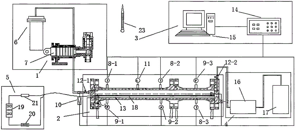
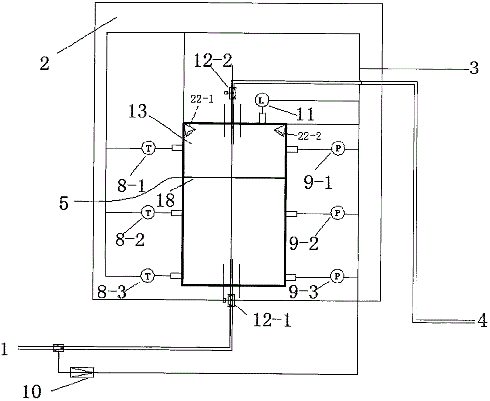
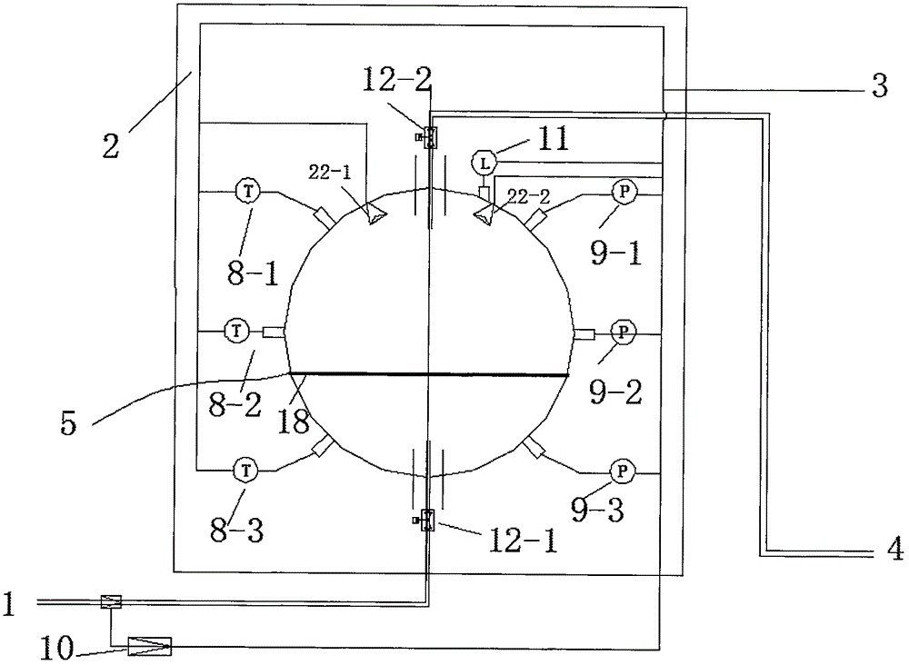
[0019] like Figure 1-5 As shown, the embodiment of the present invention provides a liquid CO 2 The phase change process simulation test system consists of liquid CO 2 Pump pressure injection system 1. Sealed high-pressure container system 2. Data acquisition and storage system 3. Waste gas and waste liquid recovery and recycling system 4. Artificial heating system 5. Five major parts, liquid CO 2 The pump pressure injection system 1 is connected with the airtight high pressure container system 2, and the airtight high pressure container system 2 is connected with the data acquisition and storage system 3, the waste gas and waste liquid recyc...


PUM


Abstract

The invention discloses a simulated testing system of a liquid-state CO2 phase change process. The simulated testing system comprises five parts including a liquid-state CO2 pump pressure injection system, a sealed high-pressure-resisting container system, a data acquisition and storage system, a waste gas and waste liquid recycling and cyclic utilization system and a manual heating system, wherein the liquid-state CO2 pump pressure injection system comprises a Dewar flask mounted beside sealed high-pressure-resisting containers and a manual variable piston pump; the sealed high-pressure-resisting container system comprises three sealed high-pressure-resisting containers with different types, including a pipeline type low-temperature-resisting and high-pressure-resisting container, a spherical type low-temperature-resisting and high-pressure-resisting container and a storage tank type low-temperature-resisting and high-pressure-resisting container; the data acquisition and storage system comprises a temperature sensor, a pressure sensor, a liquid level sensor and an infrared thermal imager which are mounted in each sealed high-pressure-resisting container. The simulated testing system disclosed by the invention can be used for monitoring changes of parameters including temperature, pressure, liquid levels and the like of liquid-state CO2 in the sealed high-pressure-resisting containers in real time; a phase state attributed graph of the CO2 is combined and phase state judgment of the CO2 in the system is realized.

Description

technical field [0001] The present invention relates to liquid CO 2 The technical field of storage safety and transportation safety, specifically relates to a liquid CO 2 Phase change process simulation test system. Background technique [0002] CO, one of the main components of greenhouse gases 2 , usually collected, stored and transported in liquid form in industrial production tail gas recovery. When liquid CO 2 When the storage temperature or pressure is below the triple point, it transforms into a solid phase. When the temperature reaches a certain value, the liquid CO 2 Vaporization, pressure rises, to liquid CO 2 The storage and transportation process has buried safety hazards. [0003] in liquid CO 2 In industrial applications, the presence of dry ice will seriously affect the liquid CO 2 Utilization efficiency may even lead to severe blockage of pipelines, and more seriously, accidents may occur, threatening the safety of staff. in liquid CO 2 During long...

Claims


Application Information

Patent Timeline
Patent Type & Authority Applications(China)
IPC IPC(8): G01N25/12
CPCG01N25/12
Inventor 马砺李珍宝郭睿智邓军程方明王伟峰王秋红魏高明
Owner XIAN UNIV OF SCI & TECH
Why Eureka
Try Eureka