Aviation non-ferrousmagnetic metal pipe fitting corrosion defect inner inspection imaging probe and method

A technology of metal pipe fittings and imaging probes, which is applied in the fields of material magnetic variables, material analysis by electromagnetic means, and measuring devices, can solve the corrosion defects of aviation non-ferromagnetic metal pipe fittings and reduce the service life of aviation non-ferromagnetic metal pipe fittings. , magnetic field gradient signal research and other issues, to achieve the effect of improving signal pickup efficiency, facilitating identification, and improving accuracy

Active Publication Date: 2017-05-10
XI AN JIAOTONG UNIV
View PDF3 Cites 7 Cited by
  • Summary
  • Abstract
  • Description
  • Claims
  • Application Information

AI Technical Summary

Problems solved by technology

[0003] Due to complex environments such as high temperature and corrosion, aviation non-ferromagnetic metal pipe fittings are prone to corrosion defects during service. The existence of such defects reduces the service life of aviation non-ferromagnetic metal pipe fittings and seriously affects flight safety. It is of great significance to image the corrosion defects of aerospace non-ferromagnetic metal pipe fittings
At present, the pulsed eddy current detection pick-up signals for corrosion defects of aviation non-ferromagnetic metal pipe fittings are mostly induced voltage signals and absolute magnetic field signals, and there is no related research on magnetic field gradient signals. There is still a gap in the research and engineering application of high-precision imaging

Method used


Image

  • Aviation non-ferrousmagnetic metal pipe fitting corrosion defect inner inspection imaging probe and method
  • Aviation non-ferrousmagnetic metal pipe fitting corrosion defect inner inspection imaging probe and method
  • Aviation non-ferrousmagnetic metal pipe fitting corrosion defect inner inspection imaging probe and method

Examples


Embodiment

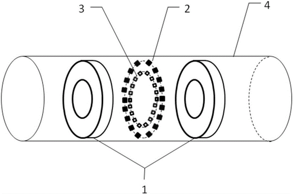
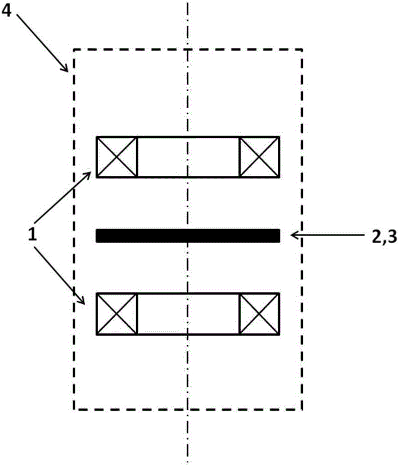
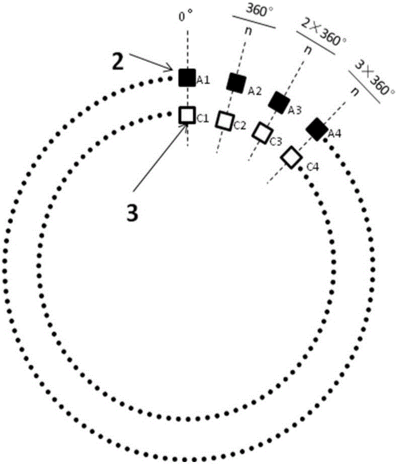
[0030] The artificial corrosion defect of the outer wall of the aerospace aluminum alloy pipe fitting is detected by using the internal detection imaging probe of the corrosion defect of the aviation non-ferromagnetic metal pipe fitting according to the present invention, the probe is placed inside the aviation aluminum alloy pipe fitting, and the aviation aluminum alloy pipe fitting is inspected along the axial direction Scanning, using the corrosion defect imaging method of the present invention, can be obtained as Figure 5 The image of the corrosion defect shown in the figure, the black area is the image of the corrosion defect obtained from the experiment, and the white solid line is the actual outline of the defect.

[0031] Depend on Figure 5 It can be seen that the imaging results of corrosion defects are very close to the actual size of corrosion defects, and the basic shape of artificial corrosion defects of aviation aluminum alloy pipe fittings can be described. I...


PUM


Abstract

The invention discloses an aviation non-ferrousmagnetic metal pipe fitting corrosion defect inner inspection imaging probe and a method. The probe comprises a pair of disk type exciting coils, an axial magnetic field gradient sensor array and a peripheral magnetic field gradient sensor array, wherein the disk type exciting coils are coaxially fixed on a photosensitive resin coil framework; the parameters of the pair of the disk type exciting coils are identical; the magnetic poles of the transient magnetic field excited by each coil are opposite; each of the axial magnetic field gradient sensor array and the peripheral magnetic field gradient sensor array comprises n equal-distance circumferential arrangement axial magnetic field gradient sensors uniformly distributed on the symmetrical surfaces of the pair of disk type exciting coils and a peripheral magnetic field gradient sensor; each axial magnetic field gradient sensor and the one peripheral axial magnetic field gradient sensor are positioned on the same radius of the circumferential arrangement. The invention also provides a detection method of the probe. The fast and high-precision imaging can be realized on the aviation non-ferrousmagnetic metal pipe fitting corrosion defects; the important engineering application values are realized.

Description

technical field [0001] The invention belongs to the technical field of non-destructive testing, and relates to an imaging probe and method for internal inspection of corrosion defects of aviation non-ferromagnetic metal pipe fittings. Background technique [0002] At present, aviation non-ferromagnetic metal pipe fittings are widely used in aircraft, aerospace / aircraft structures. The advantages of aviation non-ferromagnetic metal pipe fittings (such as aluminum alloy pipes, copper pipes, etc.) Reduce the structural weight of the aircraft, improve flight performance and increase economic efficiency. [0003] Due to complex environments such as high temperature and corrosion, aviation non-ferromagnetic metal pipe fittings are prone to corrosion defects during service. The existence of such defects reduces the service life of aviation non-ferromagnetic metal pipe fittings and seriously affects flight safety. It is of great significance to image the corrosion defects of aerosp...

Claims


Application Information

Patent Timeline
Patent Type & Authority Applications(China)
IPC IPC(8): G01N27/90
CPCG01N27/902
Inventor 李勇闫贝陈振茂敬好青张曦郁任淑廷
Owner XI AN JIAOTONG UNIV
Why Eureka
Try Eureka