Eureka AIR delivers breakthrough ideas for toughest innovation challenges, trusted by R&D personnel around the world.

SLD (superluminescent diode) light source test system

A test system and light source technology, applied in the direction of diode test, single semiconductor device test, etc., can solve the problems that cannot be directly used to measure system performance, cannot fully and accurately reflect the quality of SLD light source, and achieve direct and effective technical reference indicators Effect

Active Publication Date: 2017-05-10
北京世维通光智能科技有限公司
View PDF4 Cites 0 Cited by
  • Summary
  • Abstract
  • Description
  • Claims
  • Application Information

AI Technical Summary

Problems solved by technology

[0005] The traditional SLD light source detection method, such as measuring the P-I curve, 3dB bandwidth, spectral ripple, optical power stability and polarization degree and other parameters to judge the performance of the SLD light source, is to make the SLD light source independent of FOCT for a certain parameter A separate test cannot fully and accurately reflect the quality of the SLD light source, and the test results cannot be directly used to measure its system performance in FOCT, so it cannot provide direct and effective technical reference indicators for the screening of SLD light sources in FOCT

Method used


Image

  • SLD (superluminescent diode) light source test system
  • SLD (superluminescent diode) light source test system
  • SLD (superluminescent diode) light source test system

Examples


Embodiment Construction

[0038] Embodiments of the present invention will be further described below in conjunction with the accompanying drawings.

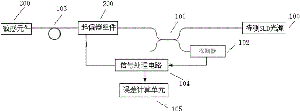
[0039] The present embodiment provides a kind of SLD light source testing system, such as figure 1 shown, including:

[0040] The first end of the coupler 101 receives the light emitted by the SLD light source 100 to be tested, and the second end is connected to the detector 102 .

[0041] The polarizer assembly 200 is connected to the third end of the coupler 101, and converts the light emitted by the SLD light source 100 to be tested into two beams of linearly polarized light, and the two beams of linearly polarized light are orthogonal.

[0042] Polarization maintaining fiber ring 103, its first end is connected with the output end of described polarizer assembly 200; Two beams of linearly polarized light enter described polarization maintaining fiber ring 103, along the fast axis and the fast axis of described polarization maintaining fiber ring res...


PUM


Abstract

The embodiment of the invention relates to an SLD (superluminescent diode) light source test system. Lights sent by a to-be-tested SLD light source pass through a coupler, a polarizer component, a polarization-maintaining fiber loop and a sensitive element and then returns by the same way, two returned linearly polarized lights interfere; a detector detects interference light intensity, and an electric signal corresponding to the interference light intensity is obtained; a signal processing circuit analyzes the electric signal sent by the detector to obtain a measured current value; and an error calculation unit obtains a measurement error introduced by the to-be-tested SLD light source in its located environment according to a reference current value and the measurement current value. As a transmission mode of a light wave in the system is the same with a light transmission mode in an FOCT (fiber optical current transformer), representation of the measurement error introduced by the to-be-tested SLD light source in the located environment also can be equivalent to an FOCT error measuring form, the scheme can completely and accurately reflect accuracy of the SLD light source, test results can be directly used for measuring system performance of the SLD light source in the FOCT, and effective technical reference is provided for screening of the SLD light source in the FOCT.

Description

technical field [0001] The invention relates to the technical field of optoelectronic devices, in particular to an SLD light source testing system. Background technique [0002] SLD (Super Luminescent Diode) light source is an essential part of Fiber Optic Current Transformer (FOCT), and the characteristics of SLD light source often play a key role in the performance of FOCT. [0003] FOCT is based on Faraday's magneto-optic effect and Ampere's loop law, and detects the magnitude of the current in the measured conductor through the optical fiber sensitive ring, specifically: when the measured conductor passes through, the left-handed and right-handed signals transmitted in the optical fiber sensitive ring The phase velocity of circularly polarized light changes in opposite directions respectively, thereby producing a phase difference proportional to the magnitude of the current (that is, Faraday phase shift), and the optical path characteristic at this time is called non-rec...

Claims


Application Information

Patent Timeline
Patent Type & Authority Applications(China)
IPC IPC(8): G01R31/26
CPCG01R31/2635
Inventor 肖浩李建光雷军刘博阳郝琰
Owner 北京世维通光智能科技有限公司
Why Eureka
Eureka Blog
Learn More