Middle-low radioactive waste treatment device

A waste treatment, low-radioactive technology, applied in the field of medium and low radioactive waste treatment equipment, can solve the problems of occupying large nuclear waste yard space, etc., and achieve good economic benefits, good curing effect, and broad market prospects

Active Publication Date: 2017-05-10
青岛天和清原科技有限公司
View PDF6 Cites 6 Cited by
  • Summary
  • Abstract
  • Description
  • Claims
  • Application Information

AI Technical Summary

Problems solved by technology

Due to the low hazard of medium and low radioactive waste, the international practice is to dig trenches about 10-20 meters deep on the ground, and then build various anti-radiation engineering barriers, and put the radioactive waste that has been incinerated, compressed

Method used


Image

  • Middle-low radioactive waste treatment device
  • Middle-low radioactive waste treatment device
  • Middle-low radioactive waste treatment device

Examples


Embodiment 1

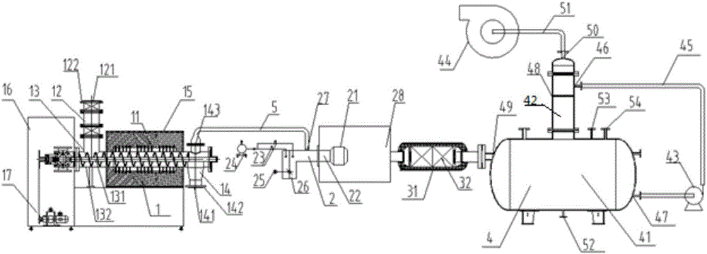
[0035] The main structure of the medium and low radioactive waste treatment device involved in this embodiment includes a pyrolysis reactor 1, a burner 2, a catalytic converter 3, a spray water washing tower 4 and a high temperature resistant pipeline 5, a pyrolysis reactor 1, a burner 2. The catalytic converter 3 and the spray washing tower 4 are connected through a high-temperature resistant pipeline 5. The pyrolysis reactor 1 includes a heating device 11, a closed feed system 12, a screw propeller 13, a closed discharge system 14, an electric Heating furnace 15, first temperature controller 16 and motor 17, closed feed system 12 includes feed inlet 121 and sealed feed valve 122, screw propeller 13 includes worm screw 131 and feed pipe 132, and closed discharge system 14 includes Solid residue outlet 141, sealed discharge valve 142 and gas outlet 143; the burner 2 includes a combustion head 21 and a burner body 22, and the burner body 22 includes a two-stage solenoid valve 23...

Embodiment 2

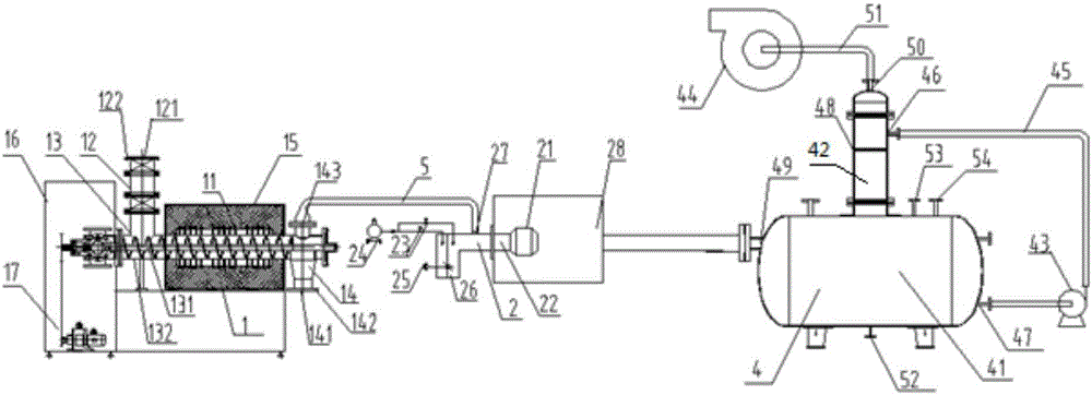
[0049] The difference between this embodiment and Embodiment 1 is that the structure of the catalytic converter 3 is omitted, and the output end of the burner 2 communicates with the second air inlet 49 of the spray water washing tower 4 through the high temperature resistant pipeline 5 .

Embodiment 3

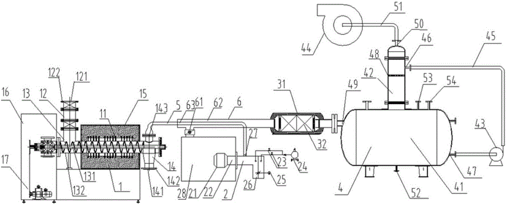
[0051]The difference between this embodiment and Embodiment 1 is: the structure of the heat exchanger 6 is added, the heat exchanger 6 is a high temperature resistant pipeline 62 with a control valve 61, and the input end of the heat exchanger 6 communicates with the exhaust gas outlet of the burner 2 , the output end of the heat exchanger 6 communicates with the catalytic converter 3, and the high-temperature resistant pipeline 62 of the heat exchanger 6 is spirally arranged on the outside of the gas inlet pipeline 63 of the burner 2, through which the high-temperature resistant pipeline 62 makes the burned The high-temperature tail gas exchanges heat with the gas at the burner 2 inlet; the difference between its processing steps and embodiment 1 is step (2), before starting the burner 2, the control valve 61 of the burner 2 tail gas outlet is opened to realize the burner 2 tail gas and The heat exchange of the inlet gas increases the temperature of the inlet gas of the burner...


PUM


Abstract

The invention belongs to the technical field of middle-low radioactive waste treatment equipment, relates to a waste treatment device, in particular to a middle-low radioactive waste treatment device. The middle-low radioactive waste treatment device is used for treating organic combustible type waste which is generated in a nuclear power plant and contains a middle-low radioactive substance, and is also used for treating middle-low radioactive waste generated in a hospital, a plant, a research institution and the like, so that volume reduction treatment and innocent treatment of the middle-low radioactive waste are achieved, and the middle-low radioactive waste treatment device comprises a pyrolysis reactor, a combustor, a catalytic converter, a spraying water scrubber and a high-temperature resistant pipeline, and all the devices are communicated through the high-temperature resistant pipeline; the middle-low radioactive waste treatment device makes it convenient for sealing up and landfill treatment of the waste, the volume reduction rate exceeds 95%, and the nuclear radiation pollution and atmospheric environmental pollution can be eliminated; a mild thermolcatalytic degradation process is adopted; the middle-low radioactive waste treatment device is simple in structure, reliable in principle, high in volume reduction rate, good in solidification effect, application environmentally friendly, low in investment and operation cost, and good in environmental protection effect, and has a good economic benefit and a wide market prospect.

Description

[0001] Technical field: [0002] The invention belongs to the technical field of medium and low radioactive waste treatment equipment, and relates to a waste treatment device, in particular to a medium and low radioactive waste treatment device, which is used to treat organic combustible materials containing radioactive substances produced by hospitals, factories, research institutions and nuclear power plants. Waste, to achieve volume reduction and harmless treatment of low- and medium-level radioactive waste. [0003] Background technique: [0004] From the technical level, radioactive waste is mainly divided into two categories: high radioactivity and medium and low radioactivity. High-level radioactive waste mainly includes spent fuel and its disposal products produced by nuclear fuel after power generation; medium and low-level radioactive waste generally includes nuclear power plant polluting equipment, testing equipment, hydration systems during operation, exchange resin...

Claims


Application Information

Patent Timeline
IPC IPC(8): G21F9/06G21F9/22
CPCG21F9/06G21F9/22
Inventor 杨成赵小鋆张伟孙强管颖
Owner 青岛天和清原科技有限公司
Why Eureka
Try Eureka