Solid oxide fuel cell stack array and power generation system thereof

A fuel cell stack, solid oxide technology, applied in solid electrolyte fuel cells, fuel cells, fuel cell grouping, etc., can solve the problems of difficult positioning and installation, no further details on how to set fasteners, and high size requirements. Achieve good and stable sealing and electrical conductivity, easy maintenance of pipelines and repairs, compact and centralized structure

Active Publication Date: 2017-05-10
NINGBO SOFCMAN ENERGY TECH CO LTD
View PDF6 Cites 14 Cited by
  • Summary
  • Abstract
  • Description
  • Claims
  • Application Information

AI Technical Summary

Problems solved by technology

The proposal specifies that fasteners are to be placed between the individual stacks, but does not further specify how the fasteners are to be placed
Moreover, the use of the device of this patent application in practice shows that in order to securely connect the battery stacks, the fasteners need to be well matched and arranged, resulting in relatively high size requirements for installation, and it is difficult to implement positioning and installation. Defects of unstable installation, resulting in unstable conduction and failure of the seal between the battery stacks, etc., all of which can further improve the design

Method used


Image

  • Solid oxide fuel cell stack array and power generation system thereof
  • Solid oxide fuel cell stack array and power generation system thereof
  • Solid oxide fuel cell stack array and power generation system thereof

Examples


Embodiment 1

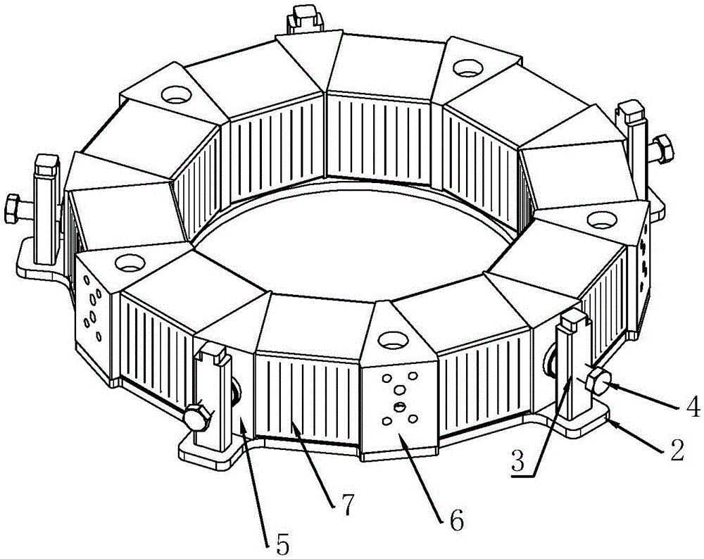
[0042] A solid oxide fuel cell stack array shown in this embodiment includes 10 cell stacks, and also includes an upper tray 1, a lower tray 2, a support column 3, a force screw 4, a movable block 5, a fixed block 6, and a cell stack 7 and other main components.

[0043] Such as figure 1 As shown, the battery stack group including 10 battery stacks 7 is placed on the lower tray 2, the battery stack 7 is in a horizontal shape, and the two sides of the battery stack 7 are respectively movable blocks 5 and fixed blocks 6, which are usually adjacent to each other in order to facilitate installation and use. A movable block 5 is set in the middle of the battery stack 7, and fixed blocks 6 are respectively set on both sides of the adjacent battery stack 7, so that the battery stacks 7 are arranged in sequence to form a layered annular distribution. As a preference, the horizontal section of the movable block 5 and the fixed block 6 is presented. Isosceles trapezoidal, the outer sur...

Embodiment 2

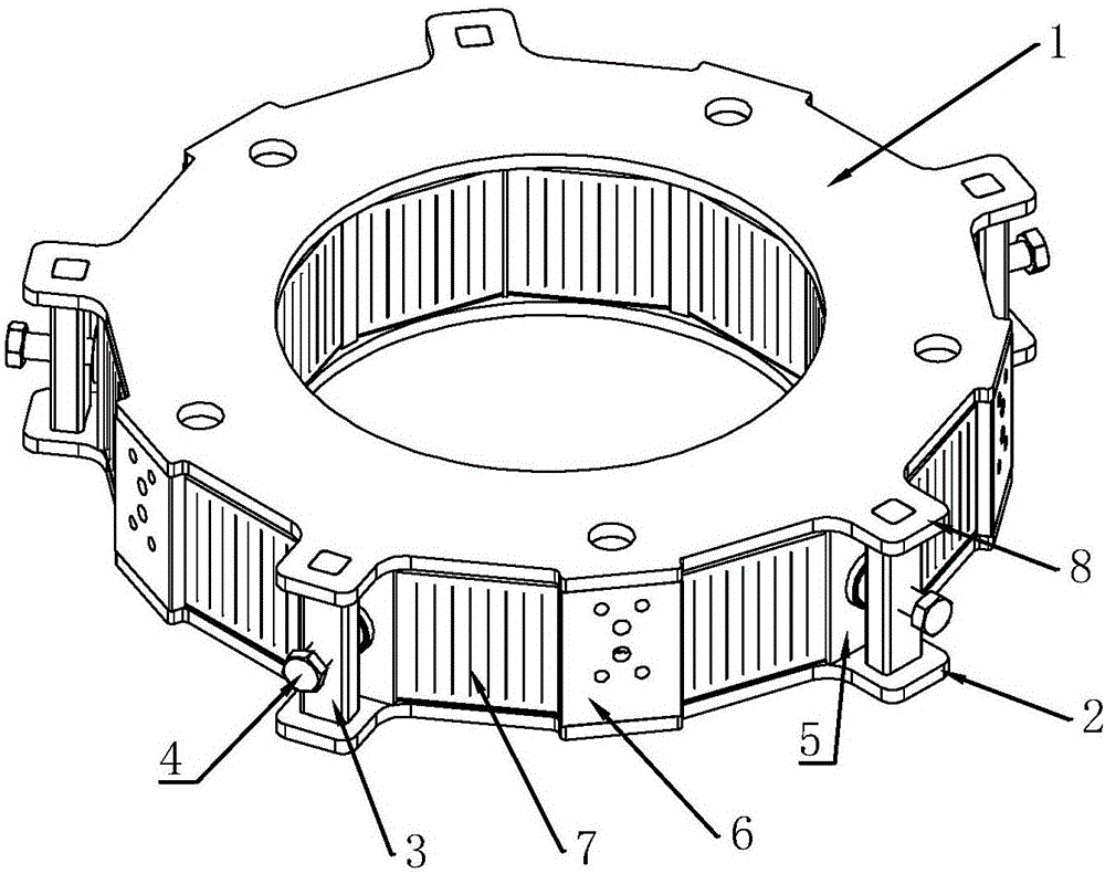
[0051] The battery stack array shown in this embodiment contains 4 battery stacks, including main components such as an upper tray 1 , a lower tray 2 , a support column 3 , a force screw 4 , a movable block 5 , a fixed block 6 , and a battery stack 7 .

[0052] Such as Figure 8 with Figure 9 As shown, 4 battery stacks are placed on the lower tray 2, and the two sides of the battery stack 7 are respectively movable blocks 5 and fixed blocks 6, on which there is an upper tray 1, and there is a support column 3 between the upper tray 1 and the lower tray 2, supporting A force screw 4 is arranged on the column 3 . When pressurizing, rotate the force-applying screw 4, and the force-applying screw 4 pushes the movable block forward, and the movable block 5 exerts pressure on the battery stacks 7 on both sides during the advancing process, so as to achieve the purpose of pressurizing the battery stack. The materials of the upper tray, the lower tray, the support column, the force...

Embodiment 3

[0056] In this embodiment, the cell stack pressurization structure in the SOFC power generation system is as follows Figure 11 As shown, it includes an upper tray 1, a lower tray 2, a support column 3, a force screw 4, a movable block 5, a fixed block 6, a battery stack 7 and other main components.

[0057] Such as Figure 11 As shown, seven battery stacks are placed on the lower tray 2, and the two sides of the battery stack 7 are respectively movable blocks 5 and fixed blocks 6, on which there is an upper tray 2, and there is a support column 3 between the upper tray 1 and the lower tray 2, supporting A force screw 4 is arranged on the column 3 . When pressurizing, rotate the force-applying screw 4, and the force-applying screw 4 pushes the movable block 5 forward, and the movable block 5 exerts pressure on the battery stacks 7 on both sides during the advancing process, so as to achieve the purpose of pressurizing the battery stack 7. The upper tray 1, the lower tray 2, ...


PUM


Abstract

The invention discloses a solid oxide fuel cell stack array and a power generation system thereof. The solid oxide fuel cell stack array comprises a support body and a cell stack group, wherein the support body is of a hierarchical structure, and at least comprises an upper tray and a lower tray; the cell stack group is carried by the lower tray; the upper tray is placed on the cell stack group; the cell stack group comprises a plurality of cell stacks; the cell stacks are horizontal; fastening pieces are arranged among the cell stacks. The solid oxide fuel cell stack array is characterized in that support columns are arranged between the upper tray and the lower tray to construct the support body; the fastening pieces on the left and right sides of the cell stacks are set as movable blocks and fixed blocks; the support columns are provided with screw holes; force application screw rods are combined with the support columns through the screw holes, and the inner ends of the force application screw rods are pressed against the outer surface of respective movable block; the strokes of the force application screw rods are adjusted through rotation of the force application screw rods, so that the side faces of the movable blocks generate pressures on adjacent cell stacks, and the cell stack group is pressed and fastened. The structure is convenient to implement, and is stable and effective.

Description

technical field [0001] The invention relates to an array structure of battery stacks in a solid oxide fuel cell (Solid oxide fuel cell, SOFC) power generation system and the power generation system thereof. Background technique [0002] The solid oxide fuel cell (Solid Oxide Fuel Cell, SOFC) power generation system can directly convert the chemical energy in the fuel into electrical energy. The fuel includes natural gas, liquefied gas, synthetic gas, biogas, hydrogen, etc. The power generation process is efficient and clean. A promising way to generate electricity. The SOFC power generation system can be modularized and integrated to build large-scale distributed power stations. The existing natural gas pipeline network can provide the natural gas required for power generation, and the generated electricity can be supplied to nearby buildings, communities, factories, etc. It can also transmit power to the national grid. Therefore, the SOFC power generation system is a power...

Claims


Application Information

Patent Timeline
Patent Type & Authority Applications(China)
IPC IPC(8): H01M8/24H01M8/2465H01M8/247H01M8/248H01M8/249H01M8/10
CPCH01M8/10H01M8/24H01M8/2465H01M8/247H01M8/248H01M8/249Y02E60/50
Inventor 王蔚国彭军陈涛何长荣牛金奇赵青
Owner NINGBO SOFCMAN ENERGY TECH CO LTD
Why Eureka
Try Eureka