
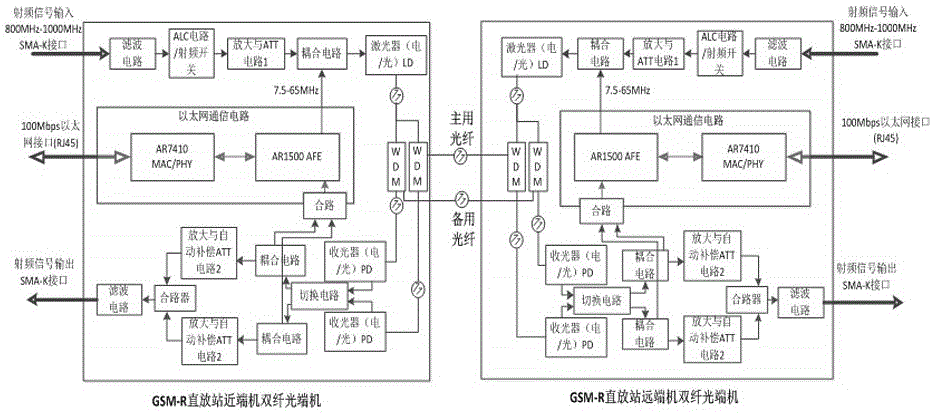
GSM-R repeater Ethernet double-fiber optical transmitter/receiver with an optical loss automatic gain compensation function

An automatic gain compensation and GSM-R technology, which is applied in electromagnetic wave transmission systems, electromagnetic repeaters, electromagnetic transceivers, etc., can solve problems such as inconsistent gain of the repeater system, poor anti-interference performance, and obstacles to the rapid development of rail transit. To achieve the effect of providing system reliability and stability and improving system stability

Active Publication Date: 2017-05-10
NANJING TICOM TECH
View PDF4 Cites 5 Cited by
  • Summary
  • Abstract
  • Description
  • Claims
  • Application Information

AI Technical Summary

Problems solved by technology

This kind of analog optical transceiver has some disadvantages: mainly low transmission rate and poor anti-interference performance, it is not suitable for the comprehensive and rapid transmission of rail transit information, which hinders the rapid development of rail transit to a certain extent
[0003] In addition, the analog repeater is affected by the length of the optical fiber in engineering applications, resulting in inconsistency in the system gain of the repeater, and the gain difference between the nearest remote unit and the farthest remote unit of the repeater may reach 10~20dB, which means that the fiber length of the farthest remote machine is 10~20km longer than that of the nearest remote machine

Method used


Image

  • GSM-R repeater Ethernet double-fiber optical transmitter/receiver with an optical loss automatic gain compensation function

Examples


specific Embodiment approach

[0036] In a specific implementation manner, the Ethernet communication circuit adopts Qualcomm Atheros AR7410 chip and AR1500 chip solution design. This design has low power consumption, high rate (physical layer rate: 600Mbps, MAC layer bandwidth: 340Mbps), embedded ARM11 CPU chip (typical main frequency 355MHz), high receiving sensitivity (≤-90dBm), advanced Turbo code front To the advantages of error correction correction. Make full use of the broadband of the existing optical devices of the analog optical module, and realize the transmission of data, voice, and video through the Ethernet protocol. The Ethernet optical transceiver module has many advantages such as high bandwidth, high security, good reliability, convenient management, and simple maintenance.

[0037] Main Specifications:

[0038] (1) Working frequency: 800~1000MHz;

[0039] (2) Gain: ≥10dB;

[0040] (3) Maximum input lossless level: ≥20dBm;

[0041] (4) ALC control range: ≥25dB;

[0042] (5) RF switc...


PUM


Abstract

The invention provides a GSM-R repeater Ethernet double-fiber optical transmitter / receiver with an optical loss automatic gain compensation function. The GSM-R repeater Ethernet double-fiber optical transmitter / receiver comprises an input radio frequency channel, two output radio frequency channels, a wavelength division multiplexing device and an Ethernet communication circuit. The input radio frequency channel comprises a filter circuit, an ALC control circuit, a radio frequency switch circuit, an amplifier circuit, an attenuator circuit, a coupling circuit and a laser circuit which are connected in sequence. Each output radio frequency channel comprises an optical receiver, a coupling circuit, an amplifier circuit, an ATT automatic compensation circuit and a filter circuit which are connected in sequence. The wavelength division multiplexing device is connected with the wavelength division multiplexing device of other optical transmitters / receivers through optical fibers or is connected with a plurality of optical transmitter / receiver modules through an optical divider. According to the GSM-R repeater Ethernet double-fiber optical transmitter / receiver, functional improvement is carried out on the basis of the existing analog optical transmitter / receiver, so the existing analog optical transmitter / receiver has the optical loss automatic gain compensation function. The optical transmitter / receiver module supports a master and standby fiber redundant communication mode.

Description

technical field [0001] The invention relates to the field of railway optical fiber communication, in particular to a GSM-R repeater Ethernet dual-fiber optical terminal with automatic gain compensation for optical loss. Background technique [0002] The analog optical transceiver module is one of the key modules of the GSM-R analog optical fiber repeater, which mainly converts GSM-R radio frequency signals into optical signals and transmits them through optical fibers. The signal transmitted by the analog optical transceiver in the optical fiber is an analog optical signal, which is cheap and commonly used. When performing data transmission, the analog optical transceiver first modulates the baseband signal into a radio frequency signal by means of FSK, and then performs electrical-optical conversion before transmission. After the optical signal is transmitted to the receiving end, it also performs optical-electrical conversion, and then performs FSK demodulation. recover t...

Claims


Application Information

Patent Timeline
Patent Type & Authority Applications(China)
IPC IPC(8): H04B10/29H04B10/40H04B7/155
CPCH04B7/15507H04B10/40H04B10/298Y02D30/70
Inventor 倪小龙吉荣新
Owner NANJING TICOM TECH
Learn More