Infrared photography optical enhancement system

An optical enhancement, infrared camera technology, applied in the field of infrared camera optical enhancement systems, can solve the problems of limiting infrared signals of a wide range of wavelengths, narrowing the research scope, etc., to improve the image signal-to-noise ratio, reduce signal interference, and facilitate Adjusted and fixed effects

Inactive Publication Date: 2017-05-10
BEIJING INSTITUTE OF TECHNOLOGYGY
View PDF5 Cites 10 Cited by
  • Summary
  • Abstract
  • Description
  • Claims
  • Application Information

AI Technical Summary

Problems solved by technology

[0003] At present, the lens is mainly used to amplify the signal. Since the infrared signal propagates in the lens, the lens has a certain thickness, which causes the infrared signal of some wavelengths to pass through well, limiting the infrared signal of a wide range of wavelengths, and narrowing the research scope.

Method used


Image

  • Infrared photography optical enhancement system
  • Infrared photography optical enhancement system

Examples


Embodiment 1

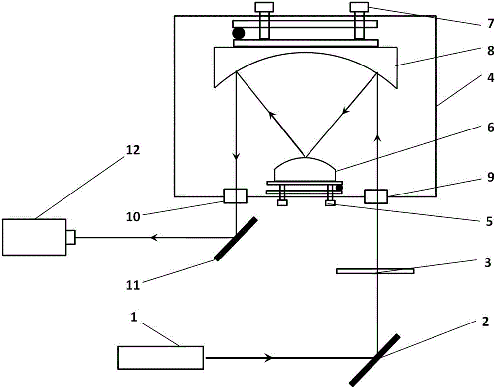
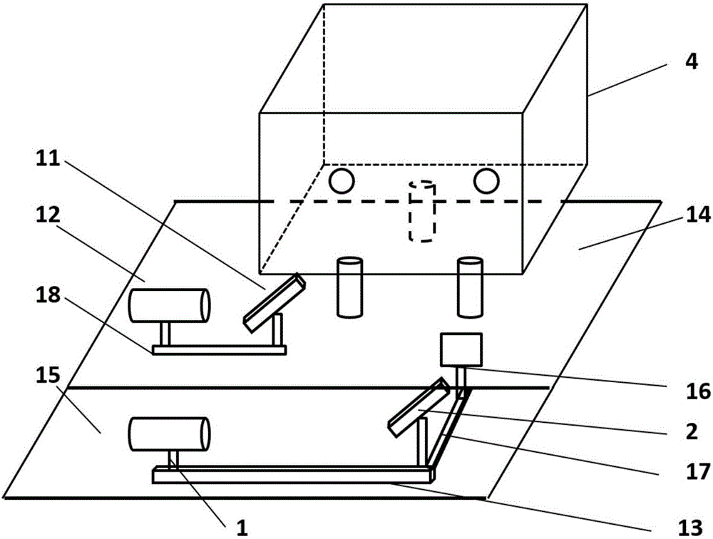
[0020] An infrared camera optical enhancement system, such as figure 1 , 2 As shown, the system mainly includes a laser 1, a first mirror 2, a grating target 3, an optical path adjustment box 4, a second mirror 11, a CCD camera 12, a fixed plate 14, and a moving plate 15;

[0021] The optical path adjustment box 4 is provided with two through holes symmetrically on the same side, and a cross plexiglass is installed at the through holes, which are the right dimming port 9 and the left dimming port 10, which are used to adjust the center of the optical path; A small adjustment frame 5, a convex mirror 6, a large adjustment frame 7 and a concave mirror 8 are placed in the box of the optical path adjustment box 4; the optical path adjustment box 4 is fixed on the fixed plate 14 by a lifting fixture; 6 is fixedly connected for adjusting the position of the convex mirror 6; the large adjustment frame 7 is fixedly connected with the concave mirror 8 for adjusting the position of the...


PUM

PropertyMeasurementUnit
thicknessaaaaaaaaaa

Abstract

The invention relates to an infrared photography optical enhancement system and belongs to the field of the high-speed temperature measurement of engineering materials and components. The infrared photography optical enhancement system is composed of a laser, reflectors, adjustment frames, a guide rail, a digital acquisition camera and the like. According to the infrared photography optical enhancement system, optical signals are transferred to a CCD camera receiver through an optical imaging system, so that a signal enhancement effect can be achieved. The invention aims to lay a foundation for the manufacture of a high-speed infrared acquisition system, thus the blockade of foreign infrared high-speed acquisition systems can be broken, and high-speed infrared photography in China can be improved. The system has the advantages of convenient operation, compact structure, high adjustment precision and the like, and can realize optical signal acquisition.

Description

technical field [0001] The invention relates to an infrared imaging optical enhancement system, which can realize optical signal enhancement and can be applied to the field of high-speed temperature measurement of engineering materials and components in combination with related testing systems. Background technique [0002] In today's international complex environment, precision guidance plays a very important role in the military field; it has become a development trend of military strategy to realize precision guidance through infrared high-speed tracking of the infrared energy radiated by the target itself. It has good concealment and Electronic interference resistance, so infrared search and track systems will play an increasingly important role in all military fields that rely on surveillance advantages; at the same time, with the wide application of composite materials in the fields of aerospace and bulletproof armor, high-speed impact damage, Deformation state and fai...

Claims


Application Information

Patent Timeline
Patent Type & Authority Applications(China)
IPC IPC(8): H04N5/33H04N5/225G01N3/06
CPCH04N5/33G01N3/068G01N2203/001G01N2203/0641H04N23/55
Inventor 陈浩森郭亚洲朱盛鑫裴永茂方岱宁陈琳
Owner BEIJING INSTITUTE OF TECHNOLOGYGY
Why Eureka
Try Eureka