
Depth map imaging device

An imaging device and depth map technology, applied in the field of image processing, can solve the problem of low imaging quality of depth maps and achieve the effect of improving quality

Inactive Publication Date: 2017-05-10
LETV HLDG BEIJING CO LTD +1
View PDF10 Cites 2 Cited by
  • Summary
  • Abstract
  • Description
  • Claims
  • Application Information

AI Technical Summary

Problems solved by technology

[0010] The purpose of the embodiments of the present invention is to provide a depth map imaging device to solve the problem of low quality of depth map imaging of virtual reality terminals in the prior art

Method used


Image

  • Depth map imaging device
  • Depth map imaging device

Examples


Embodiment Construction

[0029] In order to make the purpose, technical solutions and advantages of the embodiments of the present invention clearer, the technical solutions in the embodiments of the present invention will be clearly and completely described below in conjunction with the drawings in the embodiments of the present invention. Obviously, the described embodiments It is a part of embodiments of the present invention, but not all embodiments. Based on the embodiments of the present invention, all other embodiments obtained by persons of ordinary skill in the art without creative efforts fall within the protection scope of the present invention.

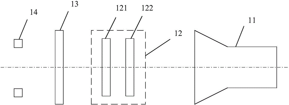
[0030] Such as figure 1 As shown, it is a schematic structural diagram of a depth map imaging device according to an embodiment of the present invention, and the depth map imaging device can be applied to various visual machines such as virtual reality terminals, robots, computers, and televisions.

[0031] The depth map imaging device includes: ...


PUM


Abstract

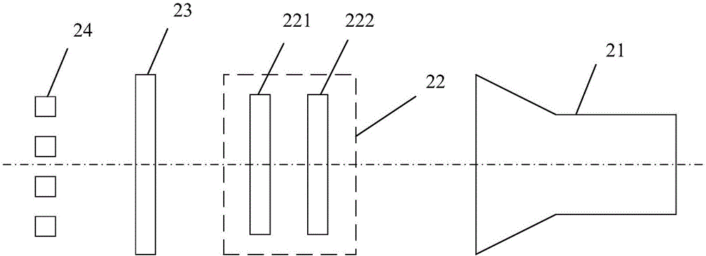
The embodiment of the invention provides a depth map imaging device, which comprises cameras, a random light spot generator, an optical filter, and one or more LED lamps. The random light spot generator further comprises lithography glass and a diffraction grating. The optical filter is positioned between the one or more LED lamps and the cameras. The random light spot generator is positioned between the optical filter and the cameras. The lithography glass is positioned between the optical filter and the camera. The diffraction grating is positioned between the lithography glass and the cameras. One image is formed by the one or more LED lamps through the lithography glass, the diffraction grating continuously copies patterns, and the thickness of the image is realized through the diffraction grating.

Description

technical field [0001] Embodiments of the present invention relate to the technical field of image processing, and in particular, to a depth map imaging device. Background technique [0002] Virtual Reality (VR, Virtual Reality) technology is a computer simulation system that can create and experience a virtual world. It uses a computer to generate a simulation environment, which is an interactive 3D dynamic scene and entity behavior system that combines multi-source information. Simulation immerses the user in that environment. [0003] In the principle of VR imaging (binocular parallax), when a person’s two eyes look at the same object, the images on the retina will be slightly different due to the different orientations of the left and right eyes, that is, binocular parallax. Two images with slight differences are displayed, and the user fuses the two images to obtain an image with a three-dimensional effect, and the imaging of the left eye and the right eye are slightly...

Claims


Application Information

Patent Timeline
Patent Type & Authority Applications(China)
IPC IPC(8): H04N13/02H04N13/04
CPCH04N13/204H04N13/225H04N13/32
Inventor 张超
Owner LETV HLDG BEIJING CO LTD
Learn More