
Compression method and device based on characteristics of flat region of image

A technology of flat area and compression method, applied in the field of image compression, it can solve the problems of neglecting pixels, interference, and large-scale noise, and achieve the effect of high flexibility and high consistency

Active Publication Date: 2017-05-10
ZHEJIANG UNIV
View PDF6 Cites 8 Cited by
  • Summary
  • Abstract
  • Description
  • Claims
  • Application Information

AI Technical Summary

Problems solved by technology

It is generally believed that the distribution of pixel values ​​in a flat area is concentrated, and the image complexity is low, and the area can be described well only by consuming a small code stream; The reconstructed image quality in flat areas is not high, and it is prone to obvious block effects
[0008] It is generally believed that the blocking effect in flat areas in image coding is caused by quantization, and a larger quantization step size used when the code rate is low will lead to greater quantization noise, resulting in more serious blocking effects
[0009] In fact, macroscopically, in a flat area where the pixel value changes relatively gently, when the image is divided into small blocks for encoding, the noise in the original image will cause great interference to the encoder, causing the encoder to make a big difference to the pixel distribution of the encoding block. It is beneficial to retain the wrong judgment of the influence of noise, resulting in a decrease in coding efficiency and coding quality
[0010] In the existing image coding standards, the compression of the flat area is described in the way that all pixel values ​​along a certain direction in the local block are equal, ignoring the overall gradient pattern of the pixels in the flat area. Representation in chunks

Method used


Image

  • Compression method and device based on characteristics of flat region of image
  • Compression method and device based on characteristics of flat region of image
  • Compression method and device based on characteristics of flat region of image

Examples


Embodiment Construction

[0063] In order to make the purpose, technical solutions and advantages of the embodiments of the present invention clearer, the technical solutions in the embodiments of the present invention will be clearly and completely described below in conjunction with the drawings in the embodiments of the present invention. Obviously, the described embodiments It is a part of embodiments of the present invention, but not all embodiments.

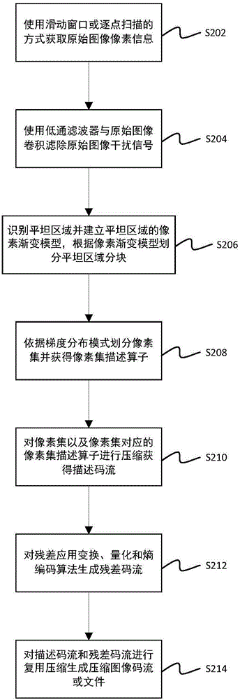
[0064] An embodiment of the present invention provides an image compression method,

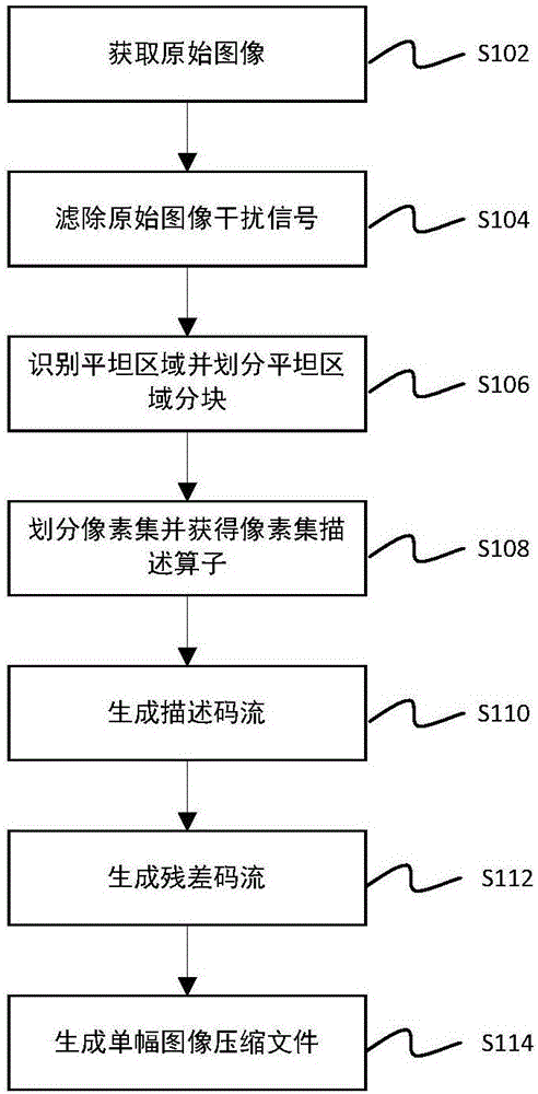
[0065] Such as figure 1 As shown, the method mainly includes the following steps:

[0066] Step S102, acquiring a single image containing a flat area that needs to be compressed; the above-mentioned single image needs to contain a large area of ​​flat area;

[0067] Step S104, filtering out the original image interference signal; since the obtained original image often contains noise and dead pixels, these interference signals may affect the identification, divi...


PUM


Abstract

The invention discloses a compression method and device based on characteristics of a flat region of an image. The method specifically comprises the following steps of (1) utilizing a single frame of a video or information of a single picture to obtain a flat region and establish a pixel gradient model of the flat region, and dividing the flat region into blocks of the flat region according to the pixel gradient model; (2) utilizing pixel information in the blocks of the flat region to obtain a gradient distribution model of the blocks of the flat region and utilizing the gradient distribution model to classify pixels included in the blocks of the flat region in order to obtain a pixel set and a pixel set description operator corresponding to the pixel set; (3) compressing the pixel set and the corresponding pixel set description operator to generate descriptor code streams; (4) utilizing the descriptor code streams to obtain a prediction image of the pixel set; compressing a residual image obtained by solving a difference of an original image of the pixel set and the prediction image to obtain residual code streams; and (5) carrying out multiplexed compression on the descriptor code streams and the residual code streams to generate compressed image code streams or files.

Description

technical field [0001] The invention relates to the field of image compression, in particular to a compression method and device based on image flat area features. Background technique [0002] The concept of single image compression is to reduce the amount of data required to represent a single digital image. Therefore, the compressed image will reduce the storage space occupied when storing the image, and the traffic / bandwidth required to transmit the image will be smaller. Therefore, image compression has a wide range of applications. [0003] The basic principle of single image compression is as follows: [0004] The reason why image data can be compressed is because there is redundancy in the data. The redundancy of single image data is mainly manifested as: spatial redundancy caused by the correlation between adjacent pixels in the image; spectral redundancy caused by the correlation of different color planes or spectral bands. The purpose of data compression is to...

Claims


Application Information

Patent Timeline
IPC IPC(8): H04N19/124H04N19/129H04N19/149H04N19/167H04N19/182H04N19/48H04N19/85
CPCH04N19/124H04N19/129H04N19/149H04N19/167H04N19/182H04N19/48H04N19/85
Inventor 王维东钱京京黄露陈彬彬
Owner ZHEJIANG UNIV
Learn More