

Method for regenerating diesel hydrocracking catalyst
A technology for hydrocracking and catalytic diesel, applied in catalyst regeneration/reactivation, metal/metal oxide/metal hydroxide catalyst, physical/chemical process catalyst, etc., can solve the reaction conversion rate, product distribution and product quality It can shorten the initial activation stability time, decrease the deactivation rate, and shorten the regeneration cycle.
- Summary
- Abstract
- Description
- Claims
- Application Information
AI Technical Summary
Problems solved by technology
Method used
Image

Examples
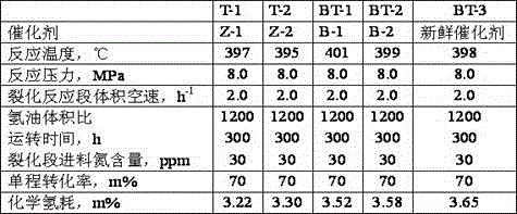
Embodiment 1
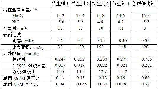
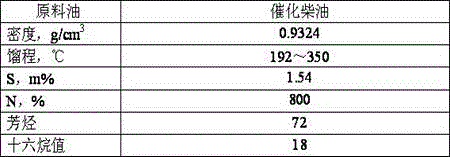
[0026] (1) Take the hydrocracking active agent 1 after the operation of an industrial device for catalytic diesel hydroconversion and put it in the regeneration furnace;
[0027] (2) Introduce an oxygen / nitrogen mixed gas with an oxygen content of 1% into the regeneration furnace, and control the gas / agent ratio of 4000:1. At the same time, raise the temperature to 370°C at a heating rate of 25°C / h, and roast at a constant temperature for 4h;
[0028] (3) Transfer the sample obtained in step (2) to a high-pressure regeneration autoclave;
[0029] (4) Introduce H into the autoclave 2 The gas is replaced, and the gas / agent ratio is controlled to be 2000:1;
[0030] (5)H 2 After replacement to an oxygen concentration of less than 0.05%, H 2 Boost the pressure to 6.0MPa, then introduce H into the autoclave 2 S gas to H 2 After the S concentration was 0.8v%, the temperature was raised to 550°C at a heating rate of 40°C / h, and treated at a constant temperature for 6 hours to ob...
Embodiment 2
[0032] (1) Take the hydrocracking catalyst standby agent 2 after the operation of a catalytic diesel hydroconversion industrial unit and place it in the regeneration furnace;
[0033] (2) Introduce an oxygen / nitrogen mixed gas with an oxygen content of 3% into the regeneration furnace, control the gas / agent ratio of 1500:1, and at the same time, raise the temperature to 350°C at a heating rate of 25°C / h, and roast at a constant temperature for 8h;
[0034] (3) Transfer the sample obtained in step (2) to a high-pressure regeneration autoclave;
[0035] (4) Introduce H into the autoclave 2 The gas is replaced, and the gas / agent ratio is controlled to be 3000:1;
[0036] (5)H 2 After replacement to an oxygen concentration of less than 0.05%, H 2 Boost the pressure to 8.0MPa, then introduce H into the autoclave 2 S gas to H 2 After the S concentration was 1.0v%, the temperature was raised to 600°C at a heating rate of 40°C / h, and treated at a constant temperature for 4 hours ...
Embodiment 3
[0038] (1) Take the hydrocracking catalyst standby agent 3 after the operation of an industrial device for catalytic diesel hydroconversion and place it in the regeneration furnace;
[0039] (2) Introduce oxygen / CO with an oxygen content of 3% into the regeneration furnace 2 Gas mixed gas, control the gas / agent ratio of 1500:1, at the same time, raise the temperature to 300°C at a heating rate of 25°C / h, and roast at a constant temperature for 15h;
[0040] (3) Transfer the sample obtained in step (2) to a high-pressure regeneration autoclave;
[0041] (4) Introduce H into the autoclave 2 The gas is replaced, and the gas / agent ratio is controlled to be 2000:1;
[0042] (5)H 2 After replacement to an oxygen concentration of less than 0.05%, H 2 Boost the pressure to 6.0MPa, then introduce H into the autoclave 2 S gas to H 2 After the S concentration was 1.0v%, the temperature was raised to 650°C at a heating rate of 40°C / h, and treated at a constant temperature for 4 hour...
PUM
| Property | Measurement | Unit |
|---|---|---|
| Specific surface area | aaaaa | aaaaa |
| Pore volume | aaaaa | aaaaa |
| Specific surface area | aaaaa | aaaaa |
Abstract
Description
Claims
Application Information