

Gradient alternating water activator
A water heater and gradient technology, applied in the field of gradient alternating water heaters, can solve the problems of large device volume, large permanent magnet material, increased cost, etc., and achieve the effect of small volume, strong surface tension and low cost
- Summary
- Abstract
- Description
- Claims
- Application Information
AI Technical Summary
Problems solved by technology
Method used
Image

Examples
Embodiment 1
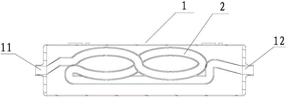
[0044] Such as figure 1 , figure 2 As shown, a gradient alternation water heater, comprising:
[0045] Housing 1; the housing is provided with a water inlet 11 and a water outlet 12 .
[0046] Water pipe 2; the water pipe is in the shape of 8, and the water pipe is arranged in the housing and the two ends of the water pipe are respectively connected to the water inlet and the water outlet.
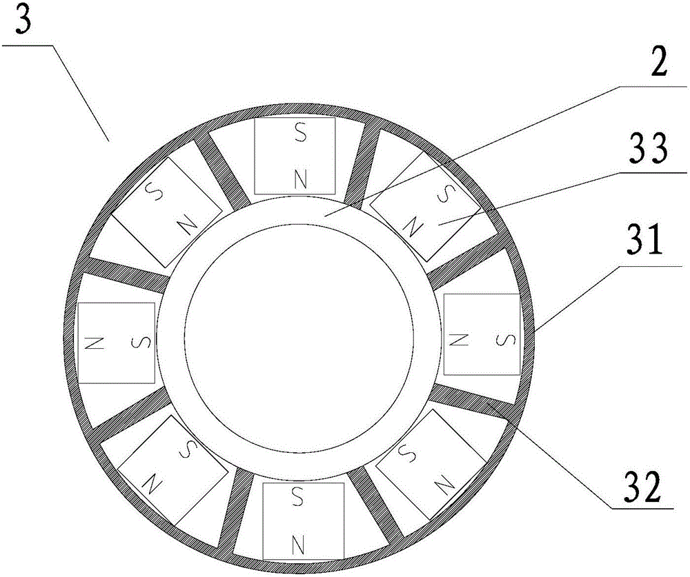
[0047] Monopole magnetic focusing device 3; several monopolar magnetic focusing devices are sleeved on the surface of the water pipe, and the gradient alternating magnetic field that completely covers the water pipe is formed by adjusting the distance between adjacent monopole magnetic focusing devices; the 8-shaped water pipe The magnetic field strength of the first S-shaped road section increases gradually, and the magnetic field strength is 3500-8000 Gauss. At the starting point of the second S-shaped road section, the magnetic field intensity drops suddenly, and then increases alon...
Embodiment 2
[0053] The difference between this embodiment and embodiment 1 is:
[0054] The magnetic shielding cover and the dividing plate of the present embodiment have a wall thickness of 5mm;
[0055] Each single unipolar magnetic focusing device in this embodiment contains 6 permanent magnet blocks; its size is 32×32×60 mm, and the magnetic poles of adjacent permanent magnet blocks facing the water pipe are opposite.
Embodiment 3
[0057] The difference between this embodiment and embodiment 1 is:
[0058] The magnetic shielding cover and the dividing plate of the present embodiment have a wall thickness of 1mm;
[0059] Each single unipolar magnetic focusing device in this embodiment contains 12 permanent magnet blocks; its size is 8×8×15 mm.
PUM
| Property | Measurement | Unit |
|---|---|---|
| Magnetic field strength | aaaaa | aaaaa |
| Magnetic field strength | aaaaa | aaaaa |
Abstract
Description
Claims
Application Information