
Device and method for cone yarn fixation aftertreatment

A post-processing device and package yarn technology, which is applied in the direction of liquid/gas/steam processing transmission device, liquid/gas/steam processing of a certain length of textile materials, textile material processing, etc., can solve problems such as uneven color fixation, To achieve the effect of improving the color fixing effect and uniform liquid retention rate

Pending Publication Date: 2017-05-17
SHANDONG JINING RUYI WOOLEN TEXTILE CO LTD
View PDF1 Cites 7 Cited by
  • Summary
  • Abstract
  • Description
  • Claims
  • Application Information

AI Technical Summary

Problems solved by technology

For the existing cheese dehydration device, please refer to the invention patent application with the application number 201510932513.0 and the name "A Kind of Cheese Dehydration Machine". It will cause the liquid-carrying rate of the package far away from the main shaft of the dehydrator to be higher than the liquid-carrying rate of the part close to the main shaft of the dehydrating machine, resulting in uneven color fixation

Method used


Image

  • Device and method for cone yarn fixation aftertreatment
  • Device and method for cone yarn fixation aftertreatment
  • Device and method for cone yarn fixation aftertreatment

Examples


Embodiment 1

[0032] The steps of using the package yarn fixation post-processing device of embodiment one:

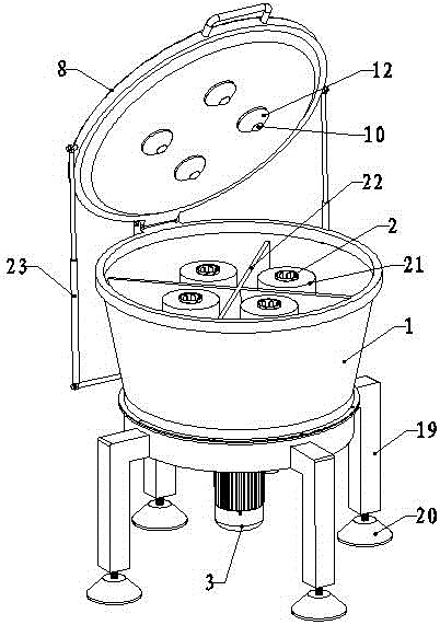
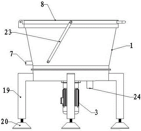
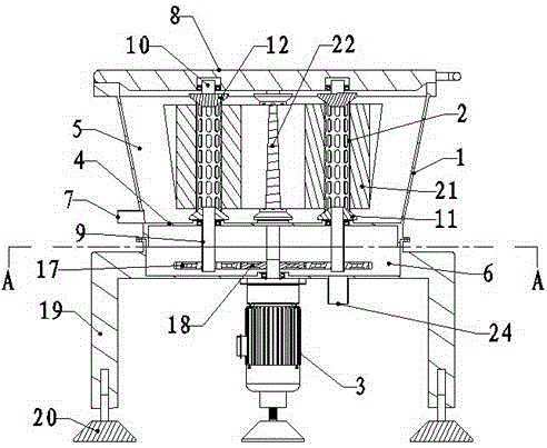
[0033] A. Install the bobbin yarn between the active bobbin shaft 9 and the driven bobbin shaft 10, start the drive motor 3, the driving motor 3 drives the active bobbin shaft 9 to rotate, the active bobbin shaft 9 drives the bobbin to rotate, and the yarn 21 Dehydration under the action of centrifugal force;

[0034] B. Start the negative pressure equipment. The negative pressure equipment sequentially passes through the negative pressure chamber 6, the active bobbin shaft 9 and the bobbin 2 to pump air inside the yarn 21, so that the alkaline solution of the part of the yarn 21 away from its mandrel is refluxed to the center , so that the liquid-carrying rate of each part of the yarn 21 is uniform.

[0035] Figure 5~Figure 7 The second embodiment of the present invention is shown. As shown in the figure, a package yarn fixation post-processing device includes a barrel body 1 , ...

Embodiment 2

[0040] The use steps of the package yarn fixing post-processing device of embodiment two comprise the following steps:

[0041] A, cheese is installed on the bobbin rotating shaft 13, start drive motor 3, driving motor 3 drives bobbin rotating shaft 13 to rotate, and bobbin rotating shaft 13 drives bobbin to rotate, and yarn 21 is dehydrated under the effect of centrifugal force;

[0042] B, start the negative pressure equipment, the negative pressure equipment passes through the negative pressure chamber 6, the yarn bobbin rotating shaft 13 and the yarn bobbin 2 in turn to draw air inside the yarn 21, so that the alkaline solution of the part of the yarn 21 away from its mandrel is refluxed to the center, In order to make the liquid carrying rate of each part of the yarn 21 uniform.


PUM


Abstract

The invention relates to the technical field of reactive dyeing equipment, in particular to a device for cone yarn fixation aftertreatment. The device comprises a barrel body, a yarn barrel rotating shaft, a yarn barrel and a driving motor. The barrel body is divided into a dehydration chamber and a negative pressure chamber by a partition plate and provided with a water outlet communicated with the lower portion of the dehydration chamber. The yarn barrel rotating shaft is installed in the dehydration chamber, the driving motor is connected with the yarn barrel rotating shaft, the yarn barrel is tubular, through holes are evenly distributed in the outer circle surface of the yarn barrel, the yarn barrel is installed on the yarn barrel rotating shaft, the yarn barrel can be communicated with the negative pressure chamber through the yarn barrel rotating shaft, and the barrel body is provided with a negative pressure device interface communicated with the negative pressure chamber. The device for cone yarn fixation aftertreatment can make the liquid carrying rate of each part uniform after cone yarn fixation, and a fixation effect is improved.

Description

technical field [0001] The invention relates to the technical field of reactive dye dyeing equipment, in particular to a package yarn fixing post-processing device and a cheese fixing post-processing method. Background technique [0002] Reactive dyes, also known as reactive dyes, are a class of dyes that chemically react with fibers during dyeing. Reactive dye molecules contain groups that can chemically react with fibers. When dyeing, the dyes react with the fibers, and form a covalent bond between the two to form a whole, which improves the fastness to washing and rubbing. It is currently widely used in cellulose Dyeing of fibers (cotton, hemp, viscose, tencel, modal, cupro, etc.), protein fibers (wool, soybean fiber, milk fiber, etc.), synthetic fibers (nylon, etc.). Reactive dye molecules include two main components, the parent dye and the active group, and the group that can react with the fiber is called the active group. The parent structure of reactive dyes is gen...

Claims


Application Information

Patent Timeline
IPC IPC(8): D06B15/10D06B5/16
CPCD06B5/16D06B15/10D06B3/36D06B23/04D06B23/042
Inventor 丁彩玲秦光尹晓品杨爱国丁翠侠刘晓飞张伟红杨晓博田刚宋亚
Owner SHANDONG JINING RUYI WOOLEN TEXTILE CO LTD
Learn More