Hydraulic pump

A technology of hydraulic pump and plunger cavity, applied in the hydraulic field, can solve the problems of heavy weight and large volume, and achieve the effect of easy processing, small volume and few parts configuration.

Inactive Publication Date: 2017-05-17
石家庄市液压有限责任公司
View PDF8 Cites 5 Cited by
  • Summary
  • Abstract
  • Description
  • Claims
  • Application Information

AI Technical Summary

Problems solved by technology

[0002] The hydraulic pumps currently used are all driven by electric motors. Since the pump and the electric motor are two separate components, they are large in size and heavy in weight.

Method used


Image

  • Hydraulic pump

Examples


Embodiment Construction

[0017] The present invention will be further described in detail below in conjunction with the accompanying drawings and specific embodiments.

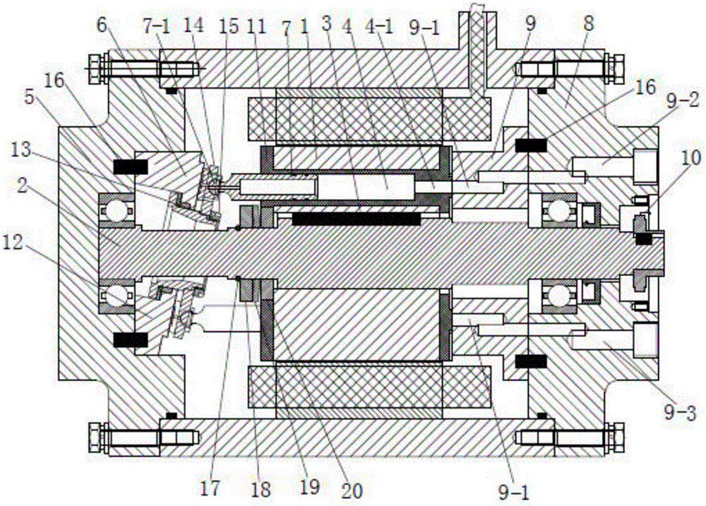
[0018] Depend on figure 1 It can be known from the shown embodiment that this embodiment includes a DC motor (24V power supply), the armature core 1 of the DC motor is connected with the motor shaft 2 through a flat key 3, and more than one hydraulic pump is arranged on the armature core 1 The plunger cavity 4, each hydraulic pump plunger cavity 4 is parallel to the axis of the motor shaft 2, and is arranged in a ring with the motor shaft 2 as the center, and the front end of the hydraulic pump plunger cavity 4 is provided with the front end cover 5 of the DC motor. The swash plate 6, the plunger 7 slidably connected with the hydraulic pump plunger chamber 4 is slidably connected with the annular sliding shoe track on the swash plate 6 through the sliding shoe 7-1 at the front end, and the sliding shoe track is located at the axis of ...


PUM


Abstract

The invention discloses a hydraulic pump. The hydraulic pump comprises a direct current motor; an armature core of the direct current motor is connected with a motor rotating shaft through a flat key; one or more hydraulic pump plunger cavities are formed in the armature core; all the hydraulic pump plunger cavities are arranged annularly with the motor rotating shaft as the center; the front ends of the hydraulic pump plunger cavities are provided with a swash plate fixed to a front end cover of the direct current motor; plungers slidably connected with the hydraulic pump plunger cavities are slidably connected with an annular slipping boot track on the swash plate through slipping boots at the front ends of the plungers; the rear ends of the hydraulic pump plunger cavities are provided with a thrust plate fixed to a rear end cover of the direct current motor; a pressing, sealed and connection structure is arranged between the armature core provided with the hydraulic pump plunger cavities and the thrust plate, specifically, a spring stopping block is arranged on the part, close to the front end of the armature core, of the motor rotating shaft, and an elastic component is arranged between the spring stopping block and the armature core so that oil passing openings in the right ends of the hydraulic pump plunger cavities can be in close fit with two waist-form flow allocation windows of the thrust plate. The hydraulic pump has the characteristics of being compact in structure, small in size, little in component configuration quantity and the like.

Description

technical field [0001] The invention relates to the field of hydraulic technology. Background technique [0002] Currently used hydraulic pumps are all driven by electric motors. Since the pump and the electric motor are two separate components, they are bulky and heavy. With the development of society, it can no longer meet the needs of some special industries such as intelligent machinery and national defense industry. Therefore, it is a trend to minimize the quality and volume. Contents of the invention [0003] The technical problem to be solved by the present invention is to provide a hydraulic pump, which has the characteristics of compact structure, small volume, and few components. [0004] In order to solve the problems of the technologies described above, the technical solution adopted in the present invention is: [0005] A hydraulic pump, comprising a DC motor, the armature iron core of the DC motor is connected with the motor shaft through a flat key, more t...

Claims


Application Information

Patent Timeline
Patent Type & Authority Applications(China)
IPC IPC(8): F04B17/03F04B1/24F04B53/10F04B53/16F04B49/06F04B51/00F04B53/00
CPCF04B17/03F04B1/2014F04B1/2035F04B1/2042F04B1/2078F04B1/24F04B49/06F04B51/00
Inventor 张巍邱叶龙
Owner 石家庄市液压有限责任公司
Why Eureka
Try Eureka